Introduction
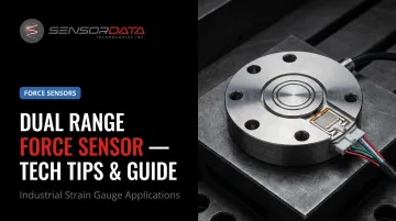
A dual-range force sensor captures both low-force detail and high-magnitude loads within a single test setup — no hardware swaps, no interruptions mid-test.
That capability only delivers value when engineers understand how each range behaves. Most measurement errors in dual-range setups trace back to range mismatches, not sensor defects:
- Applying loads outside a channel's calibrated span
- Misreading overload limits from the datasheet
- Assuming high-range calibration validates the low range
This guide covers the technical architecture behind dual-range operation, the boundary limits governing each channel, and the accuracy properties that must be evaluated independently per range. It also addresses the misapplication patterns that corrupt data or damage sensing elements.
Key Takeaways
- A dual-range force sensor provides two independently calibrated measurement spans in one sensing body; each span is a discrete, hardware-calibrated channel.
- The low range delivers higher sensitivity per unit force; the high range extends capacity at the cost of resolution.
- Each range has its own full-scale capacity, overload threshold, and accuracy envelope — selecting the wrong range directly degrades data quality.
- Calibrate and validate each channel independently — shared calibration across ranges introduces measurement error.
- Overload damage is not always visible in real time — run zero-balance checks after any near-limit event.
What Dual Range Represents in a Force Sensor
The Architecture Defined
A dual-range force sensor is a single sensing body built to deliver calibrated electrical output across two distinct full-scale spans — for example, a low-range channel at 1,000 lbf and a high-range channel at 5,000 lbf. The two ranges are accessed via separate output channels, connector pins, or switching mechanisms. This differs fundamentally from a single-range sensor, where one calibrated span covers the entire operating window.
Implementation varies by design approach. Some manufacturers use two independent bridge outputs on a single load cell body, with low/high pairings that can range from 1K/5K lbf up to 100K/270K lbf or beyond. Others use separate bridge circuits so small forces can be resolved against high initial loads — with the secondary range typically covering around 10% of the nominal force. More advanced designs support two or three independent measuring circuits in one transducer body, achieving accuracy classes from 0.02 to 0.05.
The Core Trade-Off
The low range produces more electrical output per unit force. With bridge-based sensors, rated output is expressed in mV/V — the same full-scale millivolt-per-volt output spread across a smaller mechanical span yields higher mV per newton or pound-force. That higher sensitivity is what enables fine-force resolution on the low channel.
The high range extends the measurable span at the cost of sensitivity. Fewer millivolts are available per unit force, so small force changes are harder to resolve electrically.
Range selection is the first critical setup decision in any dual-range application. Both channels are fixed by design — defined through strain gauge bridge configuration, signal conditioning electronics, or mechanical overload stops set at manufacture. Neither range is field-adjustable.
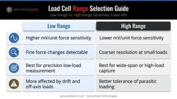
| Low Range | High Range | |
|---|---|---|
| Sensitivity | Higher mV/unit force | Lower mV/unit force |
| Resolution | Fine force changes detectable | Coarser resolution at small loads |
| Best for | Precision low-load measurement | Wide-span or high-load capture |
| Vulnerability | More affected by drift and off-axis loads | Better tolerance of parasitic loading |
Real-World Performance Factors
Because neither range can be adjusted after manufacture, real-world operating conditions become the primary variables engineers must manage. Several factors affect how each range performs in practice:
- Off-axis and parasitic loading — a given side load or bending moment represents a larger percentage of low-range full scale, so its effect on accuracy is proportionally greater on the low channel.
- Temperature fluctuation — thermal zero drift and span shift affect both channels, but the low range is more vulnerable in absolute force terms because the drift consumes a greater share of its usable span.
- Dynamic loading — ASTM E74-18e01 explicitly excludes dynamic and high-speed force calibrations from its scope; static calibration does not validate dynamic performance on either channel.
- Manufacturing tolerances — gauge bonding asymmetries between channels mean the actual usable range may be slightly narrower than the nominal specification.
Measurement Ranges, Boundary Limits, and Safe Operating Margins
Each range in a dual-range force sensor is governed by three distinct thresholds. Misidentifying any one of them risks permanent damage to the sensing element or silent loss of measurement accuracy.
| Threshold | Definition |
|---|---|
| Nominal full-scale rated capacity | The span within which linearity, hysteresis, and calibration accuracy are guaranteed |
| Safe overload limit | The maximum transient load the sensor can sustain without permanent damage |
| Ultimate mechanical limit | The load beyond which structural failure of the sensing element occurs |
Nominal Operating Range for Each Channel
The nominal full-scale range defines the span within which the sensor's published accuracy specifications — linearity, hysteresis, repeatability — are guaranteed to hold. Those guarantees carry specific assumptions:
- Temperature within the manufacturer's compensated band
- Load applied axially, not at an offset
- No prior overload events that may have shifted the zero baseline
When any of these conditions are not met, treat the published accuracy figures as estimates rather than guaranteed specifications — and document the deviation for traceability.
Overload Limits — Model-Specific, Not Universal
Overload specifications vary significantly by product. Interface's 2101 provides 4x to 5x overload protection on the lower-capacity cell. Some FUTEK products feature built-in 10x overload protection. There is no universal industry standard for "safe overload" expressed as a fixed percentage; the correct figure comes from the specific product datasheet.
One practical point: the low range typically has a tighter overload tolerance in absolute force terms, even when the percentage figures look similar to the high range. A sensing element optimized for fine resolution is not designed for structural robustness under large transient loads.
Safe Operating Margin and Fatigue Considerations
Operating chronically near the rated ceiling — even within the published safe overload limit — creates cumulative risk:
- Micro-plastic deformation in the flexural element accumulates gradually
- Zero drift develops and worsens without triggering an obvious failure signal
- Repeatability degrades silently, compromising data quality before any physical damage is apparent
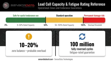
These degradation modes are detectable before failure occurs. Interface's zero-balance guidance offers a practical diagnostic: a computed zero balance of 10–20% indicates probable overload; more than 20% clearly indicates overload. Routine zero-return checks after any near-limit event should be standard procedure.
For cyclic loading applications, FUTEK's guidance is to operate at 50% or lower of rated capacity for endurance applications, or to specify a fatigue-rated sensor explicitly. Interface and PCB both publish fatigue-rated load cells guaranteed for 100 million fully reversed, full-capacity cycles — a hard performance guarantee that eliminates guesswork when qualifying sensors for high-cycle test programs.
Key Technical Properties of Dual-Range Force Sensors
Performance must be evaluated independently for each channel. A sensor that meets accuracy requirements on the high range is not automatically validated on the low range.
Sensitivity and Resolution
Sensitivity is the slope of the transducer output characteristic — the mV/V ratio. For a 2 mV/V rated output bridge at 10 V excitation, full-scale output is 20 mV. When the same electrical span covers a smaller mechanical range, each newton or pound-force produces more millivolts.
This makes range selection the primary resolution lever available to the engineer before a single reading is taken. Using the high range for forces that fall comfortably within low-range capacity wastes available sensitivity.
Linearity, Hysteresis, and Repeatability
Linearity, hysteresis, and repeatability are each specified as a percentage of full scale — and that percentage must be interpreted in the context of each channel's span:
- Nonlinearity — deviation between actual output and an ideal straight-line reference
- Hysteresis — difference in output at the same load point when approached from increasing vs. decreasing load
- Repeatability — variation among repeated outputs under identical loading conditions
A nonlinearity of ±0.1% FS represents a much larger absolute force error on the high-range channel than on the low-range channel. The percentage looks identical across both channels, but the absolute force error scales with the span — so a wider range carries a larger real-world error budget.
Temperature Sensitivity
Thermal effects manifest as zero drift (offset shift with temperature) and span shift (sensitivity change with temperature). HBK expresses the zero-signal temperature coefficient (TC₀) in %/10 K. Temperature affects both zero balance and signal output, with errors that can be positive or negative depending on the direction of change.
The low range is more vulnerable in absolute terms. A zero drift of 0.05% per 10 K means something different when full scale is 1,000 lbf versus 10,000 lbf. Temperature compensation specifications must be reviewed for the specific channel being used, not just the sensor as a whole.
Specifying and Validating Your Dual-Range Force Sensor
What a Proper Datasheet Should Contain
For a dual-range product, the datasheet and associated documentation should include:
- Separate full-scale capacity for each channel
- Rated output (mV/V) per channel
- Nonlinearity, hysteresis, and repeatability expressed as % FS per channel
- Safe overload limit and ultimate load limit per channel
- Compensated temperature range
- Range-switching mechanism details (mechanical, electrical, or software-based)
- Fatigue rating if the application involves cyclic loading
- Individual calibration certificates for each channel
A calibration certificate that covers only the high range does not validate the low-range channel. Each output must be calibrated over the span where it will actually be used.
Validation Process
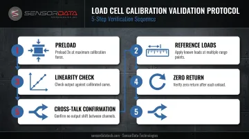
Validation should follow ISO 376:2011 principles for static force-proving instruments. The recommended sequence for each channel:
- Preload three times at the maximum calibration force before taking measurements
- Apply known reference loads at multiple points across the channel's range span
- Check output linearity against the calibrated curve
- Verify zero return after each unload sequence
- Confirm no cross-talk between channels — the high-range output should not shift when load is applied and read on the low-range channel
Morehouse notes that a force-measuring device should not be used outside the range over which it was calibrated — this applies directly to dual-range sensors used beyond their validated span.
Lab calibration conditions should reflect actual deployment conditions as closely as possible. Static calibration per ASTM E74-18e01 addresses quasi-static loading only — if the deployment involves significant loading rates or vibration, dynamic validation is a separate requirement that static procedures do not fulfill.
SensorData Technologies provides application engineering support throughout the specification and validation process, helping teams in automotive R&D, aerospace structural testing, materials testing, and defense programs select and configure dual-range sensors to match their actual calibrated operating conditions.
Risks of Operating Outside Rated Ranges and Common Misapplications
The Overload Sequence
Overload damage follows a predictable progression:
- Elastic overload — signal saturates, output becomes nonlinear; no permanent damage yet
- Beyond safe overload limit — micro-plastic deformation in the flexural element produces permanent zero shift; calibration is voided
- Beyond ultimate limit — structural failure of the sensing element; sensor replacement required
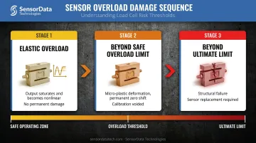
Steps 1 and 2 are rarely obvious in real time. The sensor continues to output a signal throughout — only a post-event zero-balance check reveals whether permanent damage occurred.
Common Misapplication Patterns
These are the most frequently observed errors in dual-range deployments:
- Defaulting to the high range for all measurements — if the applied forces fall well within low-range capacity, this approach discards available resolution for no benefit.
- Treating full-scale rated capacity as the maximum allowable load — full scale is the calibrated measurement ceiling, not a structural limit. The sensor may tolerate loads beyond full scale, but output above that point is uncalibrated.
- Failing to verify the active channel before logging data — if the signal conditioner is reading the high-range output while the test forces fall in the low range, the resolution and linearity figures applied to that data are wrong.
- Applying lab calibration directly to field conditions — dynamic shock loads, off-axis forces, and thermal cycling in field environments can transiently exceed the nominal range. Lab-derived assumptions do not automatically transfer to field deployments.
Cyclic loading introduces a fifth risk that doesn't appear on this list but compounds all four: fatigue failure. A standard sensor without a published fatigue rating accumulates structural damage with each cycle, with no visible indication until failure occurs. Sensors with a verified fatigue rating — guaranteed for 100 million fully reversed cycles — remove that uncertainty from the equation.
Conclusion
The dual-range architecture gives measurement engineers the ability to resolve both small and large forces in a single sensor package, which is genuinely valuable in test programs where load magnitudes vary widely across a single campaign. That value disappears when the two channels are treated as interchangeable rather than as distinct, independently calibrated measurement spans.
Each channel has its own sensitivity, accuracy envelope, overload threshold, and thermal behavior. Range selection, operating margin engineering, and per-channel calibration validation are technical decisions that directly determine whether your data is trustworthy — not administrative checkboxes.
Published specifications are starting points. Applying them correctly requires engineering judgment about actual loading conditions, the thermal environment, and the dynamic demands of the deployment.
Frequently Asked Questions
What is a dual-range force sensor?
A dual-range force sensor is a single sensing device with two independently calibrated measurement spans: a low range for high-resolution fine-force measurement and a high range for larger loads. The two channels are accessed via separate output connections or a switching mechanism, and each requires its own calibration.
What is the purpose of a force sensor?
A force sensor measures pushing or pulling forces (compression or tension) in controlled test environments and production systems. It converts mechanical force into an electrical signal proportional to the applied load, which a data acquisition system then records and analyzes.
What is a Vernier force sensor?
The Vernier Dual-Range Force Sensor is a specific product made by Vernier Science Education for lab and classroom use, offering a ±10 N low range and a ±50 N high range. The term refers to this brand's educational instrumentation. It is not a generic sensor category and is not suited for industrial, medical, or commercial applications.
What is the difference between a single-range and dual-range force sensor?
A single-range sensor is calibrated across one fixed span. A dual-range sensor provides two separately calibrated spans in one unit, offering more flexibility for test programs with varying load magnitudes — but requiring the user to actively select and validate the correct channel for each measurement task.
How do you choose which range to use on a dual-range force sensor?
Start by estimating the maximum expected force. Select the channel whose full-scale capacity exceeds that value by a safe margin, then confirm your required resolution falls within that channel's sensitivity specification. When expected forces fall within the low-range capacity, always use the low range: the higher sensitivity directly improves data quality.
What happens if you exceed the rated range of a force sensor?
Exceeding the rated range first causes signal saturation and nonlinear output. Loads beyond the safe overload threshold can produce permanent zero shift or structural damage to the sensing element. This voids calibration and may require sensor replacement. Confirm the specific overload threshold on your model's datasheet before testing.