
Introduction
In power generation, automotive testing, and industrial drives, getting excitation current to a spinning rotor means managing a short list of recurring problems: brush wear, carbon contamination, arcing in sensitive environments, and forced maintenance intervals. These aren't edge cases — they're the everyday cost of relying on slip rings and carbon brushes for rotating power transfer.
Rotary transformers solve this by transferring AC power across an air gap through electromagnetic induction, with no brushes, no contact, and no wear. The excitation systems market reflects growing adoption: Allied Market Research values the sector at $2.1 billion in 2020, projecting $3.4 billion by 2030, with brushless excitation identified as the fastest-growing segment.
What follows is a practical breakdown for engineers evaluating brushless excitation — from operating principles and geometry selection to the design parameters that determine system performance.
Key Takeaways
- Rotary transformers transfer AC power contactlessly via inductive coupling — no brushes, no wear
- Rotor excitation requires DC; a rotating rectifier converts the induced AC on the shaft
- Two primary geometries exist: disc/pancake (axial gap) and cylindrical/annular (radial gap)
- Core material selection — ferrite vs. laminated steel — depends on operating frequency
- Precision torque measurement during commissioning validates excitation system performance
What Is a Rotary Transformer?
A rotary transformer is an inductive device that transfers electrical power or signals between a stationary primary winding and a rotating secondary winding through electromagnetic coupling across an air gap. The two halves never make physical contact.
McLyman's Transformer and Inductor Design Handbook describes it as a conventional transformer arranged so that the primary and secondary can rotate relative to each other. Electrical behavior doesn't change with angular position — that 360° consistency is the core engineering achievement.
Construction and Working Principle
The device is built around two concentric, non-contacting halves:
- Stator side: Primary winding mounts on the fixed housing
- Rotor side: Secondary winding mounts on the rotating shaft
- Core geometry: Both halves (typically cup-core or annular) face each other across a small air gap
When AC voltage is applied to the primary, alternating magnetic flux crosses the air gap and induces a voltage in the secondary proportional to the turns ratio. The coupling coefficient stays consistent throughout rotation.
One critical limitation: rotary transformers only pass AC. They rely on alternating flux for induction — DC cannot be transferred this way. For rotor excitation applications where the field winding ultimately needs DC, this shapes the rectification stage covered in the next section.
How It Differs from Slip Rings
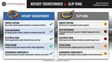
| Feature | Rotary Transformer | Slip Ring |
|---|---|---|
| Contact method | Inductive (no contact) | Direct brush-on-ring contact |
| Wear mechanism | None | Brush and ring surface wear |
| Noise | Electromagnetically clean | Electrical noise from contact resistance variation |
| Speed ceiling | High (design-dependent) | Limited by brush dynamics |
| Environment | Sealed/hazardous compatible | Arcing risk in sensitive zones |
What Is Rotor Excitation and Why Does It Matter?
In synchronous machines — alternators, generators, wound-rotor motors — the rotor winding carries a DC field current that creates the magnetic field enabling torque production or voltage generation. Without excitation, the machine is inert.
IEEE Std 1110 establishes that synchronous generator voltage stability and reactive-power capability both depend directly on excitation and field-current behavior. Getting that current to the spinning rotor reliably is the fundamental challenge.
The Problem with Brushes
The traditional approach uses carbon brushes pressing against slip rings on the shaft. It works, but the costs add up quickly:
- Electrographite brushes wear approximately 1 mm per 1,000 operating hours, with dust accumulating continuously on windings and insulation
- Brush dust degrades insulation performance over time — a slow failure mode that's easy to overlook until damage is done
- Loss of brush-to-ring contact causes arcing and rapid deterioration of operating performance, per the Combined Cycle Journal
- EPRI documents brush inspection, dust cleaning, and collector ring monitoring as recurring — and unavoidable — generator maintenance tasks
These failure modes are most costly in power plants (scheduled outage constraints), aerospace (weight and reliability requirements), and automotive test facilities (high machine utilization rates).
Brushless Excitation: The Rotary Transformer Solution
Brushless excitation replaces the brush-ring interface entirely. An AC signal passes contactlessly through the rotary transformer to the rotor. An onboard rotating rectifier then converts this AC to the DC the field winding needs. The result is fully brushless operation — eliminating wear, dust, and arcing as failure mechanisms in a single design change.
How Rotary Transformers Enable Brushless Rotor Excitation
The complete brushless excitation chain works as follows:
- Excitation control unit generates and regulates the AC supply to the primary winding
- Rotary transformer primary (stator-mounted) receives this AC power
- Rotary transformer secondary (rotor-mounted) receives magnetically induced AC across the air gap
- Rotating rectifier (diode bridge mounted on the shaft) converts AC to DC
- Main rotor field winding receives DC and generates the magnetic field
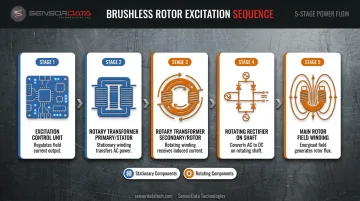
ORNL's research on wound-rotor synchronous machines confirms this architecture: the rotary transformer sits between a stationary high-frequency supply and the rotating field system, with the rotating rectifier completing the conversion to DC excitation.
Excitation Control
The AVR (automatic voltage regulator) regulates field strength by adjusting the amplitude or frequency of the AC signal at the primary winding. It senses generator output voltage and modulates excitation accordingly, giving real-time control over motor torque or generator terminal voltage. ABB and Leroy-Somer document this control loop in their generator excitation systems.
Controlling the primary signal handles the input side — but the rotor field winding requires DC, not AC. That's where the rotating rectifier completes the conversion.
The Rotating Rectifier: Essential Companion
Because the rotor needs DC and the rotary transformer delivers AC, the rotating rectifier is structurally required. A diode bridge mounted directly on the shaft converts the induced AC before it reaches the field winding. Together, the rotary transformer and rotating rectifier form a self-contained, shaft-integrated power conversion module — no slip rings, no brushes, no external DC connection to the rotor.
Reliability Advantages
Eliminating brushes removes several failure categories simultaneously:
- No maintenance intervals for brush replacement
- No carbon dust contamination of windings or adjacent equipment
- No voltage spikes from worn brushes with variable contact resistance
- Suitable for hermetically sealed environments where brush access is impossible
- No arcing risk in high-humidity or sensitive test environments
ORNL's prototype demonstrated 95.9% efficiency at 10 kW and 20 kHz, with a coupling factor of 0.956 across a 2 mm air gap — numbers that hold up at excitation-relevant power levels without physical contact.
Types of Rotary Transformers Used in Rotor Excitation Systems
Two primary geometric configurations dominate rotor excitation applications. Choosing between them depends on shaft geometry, speed, and spatial constraints.
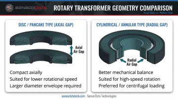
Disc/Pancake Type (Axial Air Gap)
- Primary and secondary windings face each other axially
- Flat air gap perpendicular to the shaft axis
- Compact axially, larger radially
- Better suited for lower-speed or large-diameter shaft installations
- A General Motors design referenced in ORNL research used a 0.5 mm axial air gap in this configuration
Cylindrical/Annular Type (Radial Air Gap)
- Windings are concentric around the shaft
- Air gap runs radially between inner and outer core sections
- Preferred for high-speed rotating machinery
- Provides better mechanical balance under centrifugal loading
- NASA's high-power rotary transformer study found the radial-gap design to be lighter than the pancake geometry for that design case
- ORNL's WRSM traction prototype was designed for up to 16,000 RPM
Power-Rated vs. Signal-Rated
For rotor excitation, power-rated rotary transformers are required — not signal-type devices. The power levels involved span a meaningful range across machine classes:
| Design Example | Power | Frequency | Source |
|---|---|---|---|
| ETH/APEC prototype | 200 W | 70 kHz | ETH Zurich, 2013 |
| Wisconsin synchronous machine | 400 W | — | UW-Madison thesis |
| ORNL WRSM traction motor | 10 kW | 20 kHz | ORNL, 2020 |
Signal-type rotary transformers carry only low-power measurement signals and cannot handle excitation-level power transfer. Specifying a signal-type device where a power-rated unit is needed will result in immediate thermal failure under load.
Multi-Channel Designs
Advanced systems may need to transmit both excitation power and feedback signals (rotor temperature, winding condition monitoring) simultaneously. Multi-channel rotary transformers accommodate multiple electrically isolated windings, making them practical for condition monitoring in power generation and industrial motor applications where a second signal channel would otherwise require a separate slip ring assembly.
ORNL's 2024 work on a three-phase rotary transformer for WRSM field excitation achieved higher power density by combining excitation and monitoring channels into one compact unit — a design approach that reduces axial length and eliminates a separate signal coupling component.
Key Design Parameters for Rotor Excitation Applications
Selecting the right rotary transformer for rotor excitation isn't just about matching power ratings. Five parameters drive the design decision.
Operating Frequency
Verified research confirms that rotor excitation applications favor high-frequency operation:
- Higher frequencies (20–70 kHz in documented prototypes) allow significantly smaller, lighter transformer cores
- Lower frequencies produce larger, heavier units but simplify power electronics
- Core losses increase with frequency, requiring careful material selection
The University of Wisconsin thesis on synchronous machine field excitation concludes that laminated steel suits low-frequency designs, while ferrite suits high-frequency designs. This directly ties frequency selection to core material choice.
Air Gap Tolerance and Mechanical Alignment
The air gap between primary and secondary must stay consistent across all operating conditions — rotation speed, shaft deflection, and thermal expansion. Two data points from the research illustrate the range:
- General Motors axial-gap design: 0.5 mm air gap
- ORNL WRSM prototype: 2 mm air gap, achieving 0.956 coupling factor
Larger gaps increase leakage inductance and reduce coupling efficiency. ORNL addressed this through interleaved winding geometry and resonant compensation. Precision machining of the mounting interfaces is non-negotiable — air gap variation introduces output voltage ripple that directly affects excitation quality.
Thermal Management
Rotor-mounted components (secondary winding, diode rectifier) operate with limited heat dissipation pathways. Key considerations:
- Insulation class: NEMA defines Class F at 155°C and Class H at 180°C — the rotor thermal environment determines which is required
- Core material losses: Ferrite produces lower core losses at high frequencies compared to laminated steel, reducing self-heating
- Redundancy design: Voith's maintenance-free exciter documentation notes rotating-rectifier redundancy as a design feature to handle thermal failure scenarios
Measurement Validation During Commissioning
Once the transformer design is finalized, commissioning requires validating that the excitation system delivers correct rotor field strength under actual load conditions. Accurate torque measurement is the primary tool for that verification — it confirms whether efficiency claims hold across the operating range.
For EV traction motors, alternators, and industrial synchronous drives, SensorData Technologies offers rotary transformer-coupled torque sensors such as the T211 (rated to 10,000 lb-in and 10,000 RPM) and the T114, designed for motor and generator test benches. Visit sensordatatech.com for application-specific configurations.
Frequently Asked Questions
What is a rotary transformer?
A rotary transformer is a non-contact electromagnetic device that transfers AC power or signals between a stationary primary winding and a rotating secondary winding through inductive coupling across an air gap. No brushes or physical electrical contact exist between the two halves, and coupling remains consistent across 360° of rotation.
How does a rotary transformer work for rotor excitation?
AC power is applied to the stator-mounted primary winding, magnetically induced into the rotor-mounted secondary winding across the air gap, then converted to DC by an onboard rotating rectifier to supply the rotor field winding. This chain enables fully brushless, maintenance-free excitation.
What is the difference between a rotary transformer and slip rings for rotor excitation?
Slip rings use direct brush-on-ring contact, which causes wear, carbon dust, and arcing risk. Rotary transformers use inductive coupling with no contact, offering longer service life, zero brush maintenance intervals, and compatibility with sealed or sensitive environments where arcing cannot be tolerated.
What are the main types of rotary transformers used in rotor excitation?
Disc/pancake types use an axial air gap and suit larger-diameter, lower-speed installations. Cylindrical/annular types use a radial air gap, offer better mechanical balance, and are preferred for high-speed machinery — both requiring power-rated variants capable of handling excitation-level loads.
What are the key design parameters when selecting a rotor excitation rotary transformer?
Five parameters drive the selection decision:
- Power transfer rating — matched to field winding demand
- Operating frequency — determines core size and material choice
- Air gap tolerance — requires precision machining
- Insulation class — Class F or H based on rotor thermal environment
- Core material — laminated steel for low frequency, ferrite for high frequency
In which industries are rotary transformers for rotor excitation most commonly used?
Primary applications include power generation (brushless alternators and hydro-generators), automotive and EV motor testing (wound-rotor synchronous machine traction drives), aerospace (integrated starter-generators), and industrial synchronous drives — with documented deployments across all of these sectors in IEEE and ORNL research.