Introduction
Strain gauges are only as good as the data they produce. In precision measurement applications — automotive powertrain testing, aerospace structural analysis, load cell manufacturing — even a modest temperature shift can corrupt your readings badly enough to make the data useless.
The problem is called apparent strain: a false strain signal generated by temperature alone, with no mechanical load applied. According to National Instruments, uncompensated apparent strain can reach 100 microstrain per °F (180 με/°C). In a low-load structural test where you're measuring 50–200 με of real mechanical strain, that error doesn't just distort your data — it buries it.
What follows breaks down why temperature corrupts strain data, how self-temperature compensation (STC) works, and which of the four main compensation methods fits your application — so you can stop guessing and start measuring accurately.
Key Takeaways
- Temperature causes apparent strain — false readings under zero load — due to CTE mismatch between gauge foil and substrate
- STC gauges counteract this by thermally processing the foil alloy to match a specific substrate's expansion coefficient
- STC reduces temperature-induced error but leaves a residual nonlinear error that may require computational correction
- The compensated temperature range is narrower than the operating range — confusing the two is a common measurement mistake
- Combining STC gauge selection, Wheatstone bridge wiring, and computational correction delivers the highest measurement accuracy
How Temperature Affects Strain Gauge Measurements
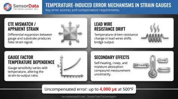
Temperature degrades strain gauge accuracy through four distinct mechanisms. Understanding each one determines which compensation strategy you need.
CTE Mismatch and Apparent Strain
The primary mechanism is a mismatch in thermal expansion. Both the test specimen and the gauge foil expand and contract with temperature. When their Coefficients of Thermal Expansion (CTE) differ (which they almost always do), the gauge registers a strain signal even under zero load. This is apparent strain, measured in microstrain (με), the same unit as real mechanical strain.
Vishay's Technical Note TN-504 shows uncompensated constantan on steel exceeding +4,000 με at 500°F. That figure isn't an edge case : it's what happens when you bond a gauge to a material without addressing CTE mismatch.
Lead Wire Resistance Drift
The second mechanism is the Temperature Coefficient of Resistance (TCR). Copper lead wires have a TCR of 3,930 ppm/°C (per NIST Handbook 100), roughly 100 to 200 times higher than typical gauge foil alloys such as constantan (~±20–30 ppm/°C).
This creates serious problems in quarter-bridge configurations with long lead runs. Vishay TT-612 documents a concrete example: a 20 ft AWG26 copper lead wire adds 1.7 Ω to a 120 Ω gauge, creating roughly 7,000 με of initial imbalance. A 10°F lead temperature change alone then produces 156 με of error.
Gauge Factor Temperature Dependence
The gauge factor (GF) , the ratio of fractional resistance change to fractional strain , also varies slightly with temperature. For constantan A-alloy, this variation is typically 1% or less per 100°F (~0.018%/°C). In most stress analysis work, this is negligible. In precision transducer manufacturing, where span accuracy is critical, it must be accounted for using manufacturer lot data.
Secondary Effects
Three additional effects affect measurement accuracy:
- Self-heating from excitation voltage raises the gauge temperature above ambient, distorting STC behavior and increasing zero-load instability . Excitation should be sized to grid area and substrate heat-sink capacity, not defaulted
- Adhesive creep at elevated temperatures softens the bond layer, reducing strain transfer efficiency
- Moisture absorption in the gauge carrier material introduces resistance shifts unrelated to mechanical strain
Each of these four mechanisms can be addressed, but only if you know which one is dominating your error budget. The compensation method that solves CTE mismatch does nothing for lead wire drift — and vice versa.
What Is a Temperature Compensated Strain Gauge?
A temperature compensated (or self-temperature compensated) strain gauge is one whose foil alloy has been thermally processed during manufacturing so its natural resistance-vs.-temperature behavior counteracts the apparent strain caused by CTE mismatch with a specific substrate. The result is a dramatically reduced thermal output over a defined temperature range.
The STC Number
The STC number identifies which substrate material's CTE the gauge has been matched to, expressed in ppm/°F or ppm/°C. You must specify the correct STC number when ordering. Common pairings:
| Substrate Material | Vishay STC Code | Approx. CTE (ppm/°C) |
|---|---|---|
| Ferritic/carbon steel, cast iron | 06 | ~11.5 |
| Austenitic stainless steel (304 SS) | 09 | ~16.7 |
| Aluminum alloys (2024-T4, 7075-T6) | 13 | ~23.2 |
| Titanium, 410 stainless | 05 | ~9.2 |
STC 06 and STC 13 are the most commonly stocked numbers for both A-alloy and K-alloy gauges.
A-Alloy vs. K-Alloy
The two main compensated foil alloys behave quite differently:
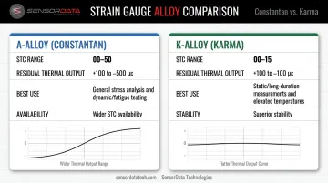
- Constantan (A-alloy): Covers the widest STC range (00, 03, 05, 06, 09, 13, 15, 18, 30, 50). Best for general stress analysis; residual thermal output runs +100 to –500 με over 0–400°F.
- Karma (K-alloy): Available in STC numbers 00, 03, 05, 06, 09, 13, and 15. Delivers a flatter output curve (+100 to –100 με), better long-term stability for static measurements, and stronger performance at elevated temperatures.
Residual Error — What STC Doesn't Fix
Even a perfectly matched STC gauge leaves a nonlinear residual thermal output. Micro-Measurements targets a total thermal response under 100 με for most applications, but the curve is not flat. Manufacturers characterize this residual error as a fourth-order polynomial and publish the coefficients in the data sheet.
Applying those published coefficients computationally corrects for the residual curve — this is how engineers close the gap between adequate and high-accuracy measurements. Without that correction step, even a well-matched gauge will introduce measurable error across wide temperature swings.
Methods of Temperature Compensation for Strain Gauges
No single method eliminates all temperature error. Practical compensation is layered.
Self-Compensated Gauge Selection
Start here. Select a gauge whose STC number matches the CTE of your test material as closely as possible. This alone eliminates the majority of apparent strain.
The intentional mismatch technique takes this further: selecting a gauge with a slightly higher or lower STC number rotates the thermal output curve about the room-temperature reference point. A lower STC number than the material's CTE rotates the curve counterclockwise; a higher number rotates it clockwise.
Engineers use this deliberately to minimize thermal output error over a specific, narrower temperature sub-range — useful when your test operates well above or below room temperature. This requires manufacturer thermal output data for the specific gauge-material combination.
Wheatstone Bridge Circuit Compensation
The Wheatstone bridge provides passive temperature compensation through symmetry. When active gauges in opposing bridge arms experience the same temperature change, the resulting resistance changes cancel in the bridge output.
Key rules for this to work:
- All gauges must be from the same foil lot
- All gauges must be bonded to the same material
- All gauges must be exposed to the same temperature environment
A half-bridge (two gauges) or full-bridge (four gauges) doubles the signal output while rejecting common-mode temperature error.
Lead wire compensation matters too:
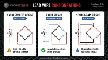
- 2-wire quarter-bridge: Lead TCR directly adds to measurement error
- 3-wire circuit: Places supply and compensation leads in adjacent bridge arms so temperature-driven changes cancel — the standard approach for remote quarter-bridge gauges
- 4-wire (Kelvin) circuit: Eliminates all cable resistance effects via separate sense leads — the most accurate option when instrumentation supports it
Computational Compensation
Residual thermal output after STC is nonlinear but repeatable, so it can be mathematically subtracted. The process:
- Measure temperature in parallel using a thermocouple or RTD at the gauge location
- Apply the manufacturer's polynomial coefficients to calculate apparent strain at that temperature
- Subtract the calculated apparent strain from the raw reading
National Instruments reports that STC gauges alone typically leave residual errors around ~10 με/°C, while software correction using manufacturer polynomial coefficients can reduce this to ~1 με/°C. That's a 10× improvement — significant in precision transducer work.
Carrier-Frequency Amplifier Technique
At junctions of dissimilar metals throughout the measurement circuit, small thermoelectric (Seebeck) voltages appear as slow DC offsets that look like zero-point strain drift. A carrier-frequency amplifier addresses this at the hardware level: it uses sinusoidal AC excitation, so the strain signal rides on the carrier frequency while the quasi-static thermoelectric DC voltage is filtered out during demodulation.
HBK's QuantumX MX1615B/MX1616B amplifiers use this approach. It's a useful complement to gauge-level and circuit-level compensation, not a replacement.
Compensated Temperature Range vs. Operating Temperature Range
These two specifications are frequently confused, and the confusion causes real measurement problems.
| Specification | Definition | Typical Range |
|---|---|---|
| Operating temperature range | Physical survival range of the gauge, adhesive, and carrier material (the limits before delamination, degradation, or mechanical failure) | Up to 300–400°C for foil; adhesive limits are often more restrictive — standard epoxies cap at 120–250°C, ceramic cements (such as Micro-Measurements HG-1) extend to 800°C |
| Compensated temperature range | The narrower range where the STC mechanism actively and accurately counteracts apparent strain | Varies by product: a TML high-temperature gauge may list –20 to +300°C operating but only +10 to +100°C compensated; another line may show –196 to +300°C operating with room temperature to +300°C compensated |
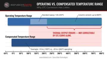
The practical consequence of confusing them: a gauge operating within its physical survival range but outside its compensated range will produce large, nonlinear thermal output errors. These errors are not predictable from the STC curve alone.
Above roughly 300–400°C, standard foil gauge compensation becomes unreliable regardless of STC number. At these temperatures, thermal output is so large and cycle-to-cycle nonrepeatable that different measurement approaches are required: weldable gauges, ceramic-bonded high-temperature gauges, or fiber Bragg grating (FBG) optical sensors. Selecting among these alternatives depends on your temperature ceiling, required accuracy, and whether the measurement point is accessible for bonding.
Choosing the Right Temperature Compensated Strain Gauge
Work through these decisions in order:
1. Identify your substrate CTE and match the STC number. Look up the CTE of your test material and select the closest available STC code. For steel structures and automotive components, STC 06 covers ferritic and carbon steel. For aluminum test rigs or aerospace aluminum structures, STC 13 is the target.
2. Verify the test temperature range falls within the compensated range — not just the operating range. Check the data sheet for both specifications. If your test runs from –30°C to +180°C, confirm the gauge's compensated range covers that span, not just that the gauge physically survives those temperatures.
3. Choose the alloy based on measurement type. Static or long-duration measurements favor K-alloy for its superior stability and flatter thermal output. Dynamic testing and fatigue studies work well with A-alloy, which offers broader STC availability and established performance across high-cycle applications.
4. Assess whether STC alone is sufficient or whether additional layers are needed.
- Automotive fatigue testing with large temperature swings during the test cycle: layer STC selection with Wheatstone bridge wiring and computational correction
- Aerospace or extreme-environment applications: verify the compensated range covers the full test envelope; standard foil gauges may fall short
- Precision transducers (load cells, torque sensors): full-bridge configurations with matched gauge lots are standard practice; residual polynomial correction is applied to meet tight accuracy specifications
When standard gauge specifications don't cover your application — whether that's a non-standard substrate, a tight STC requirement, or a fatigue-rated transducer design — SensorData Technologies offers engineering consultation backed by 30 years of custom sensor manufacturing. Contact their team directly to discuss compensation requirements for automotive, aerospace, or industrial measurement applications.
Frequently Asked Questions
What is a temperature compensated strain gauge?
It's a gauge whose foil alloy has been specially processed during manufacturing so its resistance-vs.-temperature behavior counteracts the apparent strain caused by thermal expansion differences between the gauge and the test material. This minimizes temperature-induced measurement error over a defined, specified temperature range.
How does temperature affect strain gauges?
Two primary mechanisms: CTE mismatch between gauge foil and substrate generates apparent strain — a false strain signal present even under zero load — and the high TCR of copper lead wires causes resistance changes that appear as measurement drift. Lead wire TCR (3,930 ppm/°C for copper) typically dominates in long-lead quarter-bridge setups.
What is the difference between compensated temperature and operating temperature for strain gauges?
Operating temperature is the physical survival range of the gauge and adhesive. Compensated temperature is the narrower range where the STC mechanism actively cancels apparent strain. A gauge operating within its physical survival range but outside its compensated range will produce large, uncorrected temperature errors.
What is the STC number in a strain gauge?
The Self-Temperature Compensation number indicates the thermal expansion coefficient (in ppm/°F or ppm/°C) of the substrate material the gauge is designed to match. It must be specified at the time of ordering — using the wrong STC number for your substrate produces worse results than using an uncompensated gauge.
Can a temperature compensated strain gauge be used on a material other than its matched substrate?
Yes, but a mismatched STC number renders the built-in compensation ineffective or counterproductive. Intentional STC mismatch (curve rotation) is a valid technique when you have the manufacturer's thermal output data and understand how the curve shifts for your specific temperature range.
When is computational compensation needed in addition to a self-compensated gauge?
Computational compensation becomes necessary in three situations:
- The test temperature range is large and the STC gauge's residual nonlinear error is significant relative to measured strains
- A precisely matched STC gauge is unavailable for your substrate
- Accuracy requirements demand the ~1 με/°C performance that polynomial correction enables, versus the ~10 με/°C typical of STC alone