
That measurement comes from strain gauges. They're the most widely used tool in experimental stress analysis, found in everything from bridge monitoring systems to fatigue test rigs in automotive labs.
This article covers how strain gauges work, the role of the Wheatstone bridge in extracting usable signals, the main gauge types and patterns, where they're used across industries, and the factors that determine measurement accuracy.
Key Takeaways
- Strain gauges measure deformation electrically — resistance changes as the foil stretches or compresses with the test surface
- A Wheatstone bridge converts those tiny resistance changes into a measurable voltage output
- Quarter-, half-, and full-bridge configurations trade off sensitivity against temperature compensation — choose based on your accuracy requirements
- Temperature, bonding quality, and EMI are the primary sources of measurement error
- Rosette gauge patterns resolve principal strain direction when load orientation is uncertain
What Is a Strain Gauge?
Strain, Stress, and Why This Matters
Strain is defined as the ratio of a material's change in length to its original length (ΔL/L). It's dimensionless and expressed in microstrain (µε), where 1 µε = 1 × 10⁻⁶ m/m. Tensile strain is positive; compressive strain is negative.
The actual target in most structural analysis work is stress, not strain. Hooke's Law (stress = modulus of elasticity × strain) gives engineers the conversion — measured strain becomes the stress values needed for structural decisions. Since direct stress measurement isn't physically possible, the strain gauge provides the practical path to it.
Physical Construction
A bonded metallic foil strain gauge consists of three main elements:
- A metallic foil grid etched into a zig-zag pattern from resistive alloy (typically constantan or karma)
- A flexible backing (carrier) made from polyimide film, glass-fiber-reinforced epoxy-phenolic resin, or similar electrical insulation materials
- An adhesive layer that bonds the assembly to the test surface
The design dates to 1938, when Professor Arthur C. Ruge at MIT and Edward E. Simmons at Caltech independently developed the bonded resistance strain gauge — the same fundamental concept used today.
How a Strain Gauge Works
The Piezoresistive Effect
When a conductive material is stretched, it becomes longer and thinner, increasing electrical resistance. When compressed, it shortens and widens, decreasing resistance. This change in resistance is directly proportional to the applied strain.
The relationship is captured by the gauge factor (GF):
GF = (ΔR/R) ÷ ε
where ΔR/R is the fractional change in resistance and ε is the mechanical strain. Metallic foil gauges typically have a GF of approximately 2. Semiconductor gauges reach GF values of 50–200, but that higher sensitivity comes with trade-offs:
- Metallic foil: GF ≈ 2 — stable across temperature, durable under shock and vibration
- Semiconductor: GF 50–200 — high sensitivity for dynamic applications, but prone to temperature drift and mechanical shock damage
Why the Zig-Zag Grid?
The zig-zag pattern maximizes conductive material aligned with the measurement direction within a compact footprint. This allows gauges as small as 0.2 mm grid length (TML catalog data) while maintaining sensitivity without excessive heat buildup at higher excitation voltages.
Signal Output — The Core Challenge
The resistance changes involved are extremely small. At 1,000 µε, a quarter-bridge configuration produces roughly 0.5 mV per volt of excitation — a 5V supply yields just 2.5 mV of output. At that level, both a Wheatstone bridge and signal conditioner are required to extract usable data.
The Wheatstone Bridge and Signal Conditioning
Bridge Fundamentals
The Wheatstone bridge arranges four resistive arms in a square formation with an excitation voltage source and a differential voltage detector across the opposite nodes. With no strain applied, the bridge is theoretically balanced — output voltage is zero. Any strain-induced resistance change tips that balance and produces a measurable voltage.
Three standard configurations exist:
| Configuration | Active Gauges | Typical Sensitivity | Primary Advantage |
|---|---|---|---|
| Quarter-bridge | 1 | ~0.5 mV/V at 1000 µε | Simplest setup |
| Half-bridge | 2 | ~0.65–1.0 mV/V | Doubles output, partial temperature compensation |
| Full-bridge | 4 | ~1.3–2.0 mV/V | Maximum sensitivity, best temperature rejection |
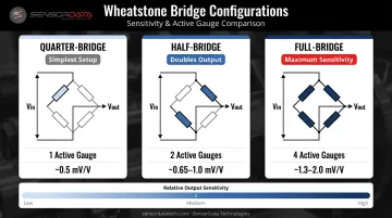
More active gauges increase sensitivity and enable cancellation of unwanted strain components — for example, a half-bridge bending configuration rejects axial load.
Signal Conditioning Requirements
Signal conditioning covers three core functions:
- Supplies stable excitation voltage — typically in the 3–10V range; instability here directly becomes measurement error
- Amplifies the output — bridge outputs in the ±10 mV range require precision instrumentation amplifiers before any analog-to-digital conversion
- Applies bandwidth filtering — limits noise from mechanical vibration and electrical interference
SensorData Technologies' BT4000 series sensors embed all three functions directly at the sensor level — handling excitation, amplification, and 16-bit digital conversion, then transmitting data wirelessly via 2.4 GHz Bluetooth rather than routing analog signals to a separate conditioner.
Handling the Static Offset
Signal conditioning handles amplification and filtering, but there's a separate challenge that comes before either: the bridge rarely reads exactly 0V at rest. Resistor tolerances, lead wire resistance, and installation-induced pre-strain all introduce a DC offset. This is corrected either through hardware balancing (parallel trim resistors) or software auto-zeroing — with the distinction mattering most when measuring static (not purely dynamic) strain, where that offset can't simply be filtered out.
Types of Strain Gauges and Gauge Patterns
Bonded Metallic Foil Gauges
The standard for most stress analysis work, with these key characteristics:
- Suitable for both static and dynamic measurements
- Available in grid lengths from 0.2 mm to 100+ mm
- Adhesive choice affects service life: cyanoacrylate (M-Bond 200) suits short-term installations at moderate temperatures; epoxy types (M-Bond AE-10, M-Bond 610) handle long-term or elevated-temperature applications up to 750°F
Foil gauges cover the majority of industrial stress analysis applications, but an alternative exists for cases demanding higher sensitivity.
Semiconductor (Piezoresistive) Gauges
Higher gauge factors (50–200) make these more sensitive, but their drawbacks limit applicability:
- Significant drift under sustained static loads
- More sensitive to temperature variation
- Higher susceptibility to mechanical shock
- Best suited for short-duration dynamic testing where high sensitivity outweighs the need for long-term stability
Gauge Pattern Selection
Choosing the right pattern depends on what you know about the stress state:
- Linear (uniaxial) — for measurements along a known strain direction
- Tee (90° two-element rosette) — for biaxial stress states where principal directions are known
- Three-element rosette (45° rectangular or 60° delta) — for situations where principal strain directions are unknown; allows calculation of both principal strains and maximum shear stress
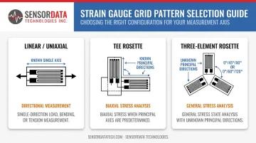
When in doubt about principal directions — common in complex geometries — the three-element rosette is the safe default for general-purpose stress surveys.
Key Applications Across Industries
Force, Torque, and Pressure Transducers
Strain gauge principles are the foundation of load cells, force transducers, torque sensors, and pressure sensors. The gauge converts mechanical deformation into a resistance change; the Wheatstone bridge converts that into a calibrated electrical output.
SensorData Technologies manufactures sensors built on these principles for automotive, aerospace, military, medical, and structural testing customers. Their product line includes:
- Fatigue-rated load cells guaranteed for 100 million fully reversed cycles
- Slip ring and rotary transformer torque sensors
- Multi-axis force/torque sensors
- The M211-114 combined torque/thrust sensor used in tire testing rheometers
These applications span across industries where mechanical loading must be precisely characterized — which is where structural monitoring demands its own set of tools.
Structural Health Monitoring
Strain gauges embedded in or attached to bridges, aircraft, and industrial structures detect fatigue accumulation, creep, and damage before failures occur. According to ASCE's 2025 Infrastructure Report Card, 6.8% of U.S. bridges are in poor condition, with a 10-year funding gap of $373 billion — making continuous monitoring a practical necessity, not just an engineering preference.
Real deployments include the Indian River Inlet Bridge in Delaware, which used 240 sensors — including weldable foil strain gauges — to monitor construction loads and service-life response (FHWA, 2014).
Material and Component Testing
In fatigue testing laboratories, strain gauges quantify how materials respond to repeated loading cycles — the data used to characterize fatigue limits, validate FEA models, and certify components for lifecycle requirements. NASA's load calibration programs on aircraft structures and ASTM E606/E606M-21 strain-controlled fatigue testing both depend on precision gauge measurements.
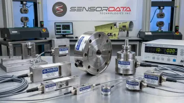
SensorData's fatigue-rated sensors, including the F312 and M231 series, serve exactly this application profile — material testing machines, airframe test fixtures, and component lifecycle certification rigs.
What Affects Strain Gauge Measurement Accuracy
Temperature
Temperature is the dominant environmental error source. Thermal expansion of the test object changes gauge resistance independently of mechanical strain, creating false readings. Two standard compensation strategies address this:
- Self-temperature-compensated (STC) gauges — matched to the thermal expansion coefficient of the test material; thermal output is minimized over a specified temperature range
- Dummy gauge technique — an identical gauge bonded to an unstrained reference specimen at the same temperature, wired into an adjacent bridge arm to cancel thermal effects
Bonding Quality
The adhesive layer must transmit strain faithfully. Any compliance or air gap between gauge and surface introduces creep, hysteresis, and instability. HBK quantifies this: with a lower-performance adhesive at 70°C and 2,000 µε loading, deviation reaches -5% within one hour.
Proper surface preparation is required before bonding:
- Degrease the surface to remove oils and contaminants
- Smooth to the appropriate finish for the adhesive system
- Dry thoroughly before applying the gauge
EMI and Environmental Factors
Because strain gauge output is in the millivolt range, electrical noise from nearby equipment can overwhelm the signal. Standard mitigations:
- Shielded cables with shields grounded at the instrument end
- Proper circuit grounding and separation from power conductors
- Protective coatings against moisture, which introduces parasitic resistance in lead wiring
Gauge Selection
Choosing the wrong gauge introduces systematic error before installation begins. Match each parameter to your application:
- Grid resistance — higher resistance (350Ω vs. 120Ω) reduces self-heating at a given excitation voltage
- STC number — must match the thermal expansion coefficient of the test material
- Gauge length — longer gauges average over surface area (useful for heterogeneous materials); shorter gauges resolve steep strain gradients
- Backing material — determines operating temperature range and chemical compatibility
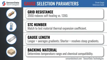
Factor total installation cost into the decision, not gauge price alone.
Frequently Asked Questions
How does a strain gauge work?
A strain gauge measures the change in electrical resistance of a conductive foil as it deforms along with the test object's surface. This resistance change is proportional to applied strain and is converted to a readable voltage output via a Wheatstone bridge circuit connected to a signal conditioner.
What is a strain gauge used for?
Strain gauges measure mechanical strain in structural and mechanical components, validate structural integrity, and serve as the core sensing element inside load cells, force transducers, torque sensors, and pressure sensors — across aerospace, automotive, civil engineering, and medical device testing.
How accurate is a strain gauge?
With proper installation, calibration, and temperature compensation, bonded foil gauges can resolve strains in the single microstrain (µε) range. Actual accuracy depends heavily on bonding quality, signal conditioning performance, temperature management, and correct gauge selection for the application.
Is it "strain gauge" or "strain gage"?
Both spellings refer to the same device. "Strain gauge" is the standard international spelling; "strain gage" is the preferred American engineering spelling used by manufacturers like Micro-Measurements and the experimental stress analysis community in the U.S.
What is the Wheatstone bridge and why is it used with strain gauges?
The Wheatstone bridge is a four-arm resistive circuit that converts a strain gauge's small resistance changes into a measurable differential voltage. It provides a balanced zero-output reference at rest and enables temperature compensation when dummy or active gauges occupy adjacent arms.
What is the difference between a quarter-bridge, half-bridge, and full-bridge configuration?
These terms indicate how many active strain gauges are wired into the Wheatstone bridge: one, two, or four. More active gauges produce higher output sensitivity and better rejection of temperature effects and cross-sensitivity from bending or axial loads.