Introduction
A miscalibrated force probe doesn't just produce bad data. It can trigger product failures, structural damage, and in regulated industries, serious safety consequences. The FDA's 2023 Class 2 recall of Medfusion infusion pumps cited a force sensor in the occlusion detector drifting out of calibration, potentially causing false alarms or system failures. That's one real-world example of what happens when force measurement goes wrong.
Yet force probes remain widely misunderstood. Engineers frequently conflate the terms "force probe," "force transducer," "force sensor," and "load cell" — and the confusion doesn't stop at terminology. Many don't fully grasp how the underlying measurement technology affects output accuracy, sensor longevity, or application suitability.
This guide cuts through that confusion. By the end, you'll know:
- What a force probe is and how it differs from related sensor types
- How force converts into an electrical signal at the hardware level
- The major sensing technologies and where each fits
- Why calibration is non-negotiable — and what happens when it's skipped
- How to select the right probe for demanding industrial applications
Key Takeaways
- Force probes, force transducers, load cells, and force sensors are largely interchangeable terms; differences lie in calibration and application context
- Most industrial force probes use strain gauge technology and a Wheatstone bridge circuit to convert deformation into a measurable voltage
- Calibration corrects zero offset, nonlinearity, hysteresis, and temperature drift; skipping it invalidates measurement data
- Technology selection (strain gauge vs. piezoelectric) depends on whether loading is static or dynamic
- Fatigue-rated sensors are a distinct engineering category, required for high-cycle endurance testing
What Is a Force Probe?
A force probe is a precision measurement device that detects and quantifies applied mechanical force — whether in tension, compression, shear, or a combination — and converts it into a measurable electrical output. The device sits within the force flow of a system, responds to mechanical deformation, and produces a signal proportional to the magnitude of applied force.
Manufacturers use "force probe," "force transducer," "force sensor," and "load cell" almost interchangeably — FUTEK's product catalog groups all three under a single page. The practical distinction most engineers rely on: load cell typically implies a strain gauge-based static sensor calibrated in weight units, while force transducer emphasizes measurement in Newtons or pounds-force.
No standards body cleanly separates the terms, so the choice usually comes down to industry convention and what your data acquisition system expects as input.
Where Force Probes Are Used
Force probes appear wherever quantified force data drives a decision:
- Automotive component labs — powertrain load testing, durability validation
- Medical device assembly — grip force verification, occlusion detection
- Aerospace and structural testing — airframe fatigue rigs, static proof loading
- Material testing machines — tension, compression, and fatigue characterization
- Machine monitoring — real-time load trending on production equipment
- Quality control lines — pass/fail force checks on assembled components
That reach is substantial. The global force sensor market was valued at $2.30 billion in 2024 and is projected to reach $3.93 billion by 2035, driven by expanding automation and tighter quality requirements across manufacturing sectors.
How a Force Probe Works: The Measurement Process
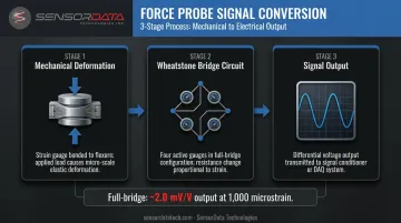
A strain gauge-based force probe converts mechanical force into an electrical signal through three sequential stages: mechanical deformation → resistance change → voltage output.
Stage 1 – Mechanical Input and the Sensing Element
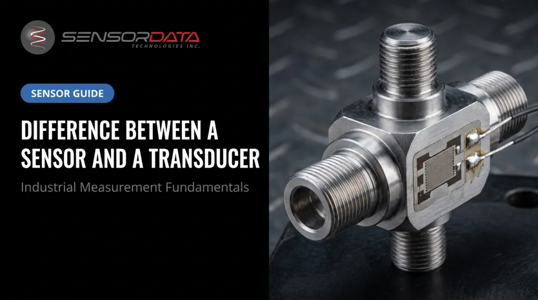
When force is applied, the probe's metal body (called the flexure) deforms elastically. Bonded to this flexure are strain gauges: thin foil elements whose electrical resistance changes in direct proportion to their physical elongation or compression.
The flexure material governs how much deformation occurs for a given load. Stainless steel (roughly 180 GPa Young's modulus) deforms less than aluminum (69 GPa), making material selection a deliberate engineering tradeoff between sensitivity and stiffness.
Factors that affect sensing element performance:
- Probe tip geometry and contact area
- Flexure material and heat treatment
- Temperature and humidity (both introduce measurement drift if unmanaged)
- Tuning fork vs. standard flexure geometry
Stage 2 – The Wheatstone Bridge Circuit
Strain gauges are wired into a Wheatstone bridge circuit, typically a full-bridge configuration using four gauges. When no force is applied, the bridge is balanced and outputs zero. Any applied force unbalances the bridge and produces a differential voltage proportional to the load.
A full-bridge configuration at 1,000 microstrain outputs approximately 2.0 mV/V, four times the sensitivity of a quarter-bridge at the same strain level. The full-bridge design also provides built-in temperature compensation, since thermal effects on all four gauges cancel each other out — a critical benefit in industrial environments where ambient temperature fluctuates.
Stage 3 – Signal Output and Data Acquisition
That differential voltage exits the bridge as a raw millivolt-per-volt (mV/V) signal, too weak for most downstream systems on its own. A signal conditioner or amplifier:
- Supplies regulated excitation voltage to the bridge
- Amplifies the mV/V output
- Filters electrical noise
- Converts the signal to a usable form: analog (0–10 V, 4–20 mA) or digital (USB, SPI, UART)
The conditioned signal feeds a computer, PLC, or DAQ system for real-time display and logging. That complete chain from physical force to actionable data is the force measurement system. Calibrating only the sensor and ignoring the signal conditioning electronics introduces system-level error that individual component specs won't catch.
Types of Force Probes and Transducers
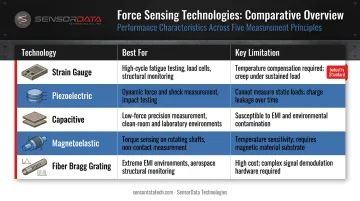
Technology selection has direct consequences for accuracy, response time, dynamic range, and how well the sensor handles static versus cyclic loading.
| Technology | Best For | Key Limitation |
|---|---|---|
| Strain gauge | Static and quasistatic loads | Slower response than piezoelectric |
| Piezoelectric | High-speed dynamic measurement | Cannot measure true static loads |
| Capacitive | Low forces, overload-tolerant designs | Less common in high-force industrial use |
| Magnetoelastic | High-EMI environments, bolt-load | Specialized; not general-purpose |
| Fiber Bragg grating (optical) | Electrically isolated, high-precision | Higher cost, specialized readout |
Strain Gauge Force Probes
Strain gauge probes dominate industrial force measurement. According to Omega Engineering, strain gauge load cells offer accuracies from 0.03% to 0.25% full scale — sufficient for virtually all industrial applications. They handle capacities from a few grams to tens of thousands of pounds, exhibit low drift, and maintain stable long-term output.
Common form factors, each suited to different load paths:
- S-beam — tension and compression, inline loading
- In-line/canister — push/pull applications with threaded ends
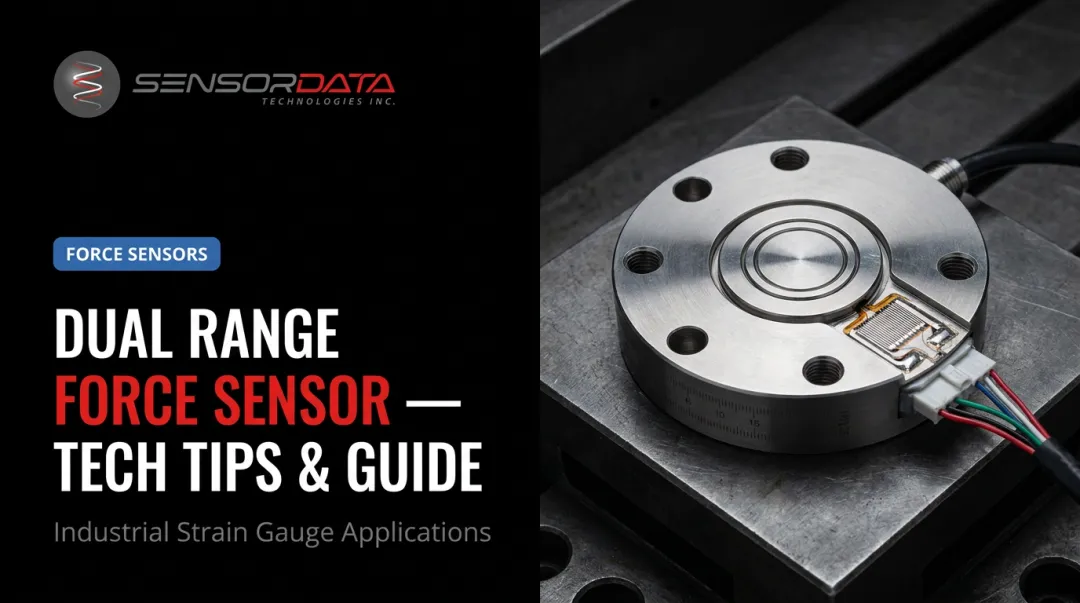
- Pancake/shear web — low-profile, high durability, minimal moment sensitivity
- Load button — compact compression-only measurement
- Thru-hole — bolt-load measurement through the sensor body
Beyond form factor, fatigue-rated variants form a distinct subcategory engineered specifically for high-cycle endurance. SensorData Technologies' fatigue-rated load cells are guaranteed against fatigue failure for 100 million fully reversed cycles — a specification grounded in their use of SAE/AISI 4340 alloy steel, which maintains structural integrity at stress levels where standard steels fail within tens of thousands of cycles.
Piezoelectric Force Probes
Piezoelectric sensors generate electrical charge when crystalline material is mechanically stressed. They excel in dynamic work: roughly 10 times stiffer than resistive-element load cells and with a frequency response about 10 times higher.
The critical limitation: piezoelectric sensors cannot measure true static force. Charge output decays over time, making them unsuitable for sustained or slowly varying loads. Use them for high-speed impact, dynamic cutting force, or vibration measurement — not for long-term static monitoring or fatigue testing.
Other Force Sensing Technologies
- Capacitive — measures distance change between plates under load; high overload tolerance (up to 1,000% in some designs), well-suited for low-force and soft-contact applications
- Magnetoelastic — based on the Villari effect, where mechanical stress in ferromagnetic material changes magnetic flux; suited to high-EMI environments and bolt-load monitoring
- Fiber Bragg grating (optical) — light wavelength shifts proportionally to strain; electromagnetically immune, intrinsically safe, and capable of multiplexing up to 16 sensors on a single optical fiber
- Multi-axis — measures force and torque simultaneously across multiple spatial directions; used in robotics, advanced testing rigs, and six-degree-of-freedom load characterization
Why Force Probe Calibration Is Non-Negotiable
Even a high-quality sensor produces erroneous data without proper calibration. The error sources it addresses are cumulative:
- Zero offset — output at zero load (non-zero baseline)
- Nonlinearity — deviation from an ideal linear response across the measurement range
- Hysteresis — difference in output when approaching a load from above vs. below
- Repeatability errors — variation across multiple identical load applications
- Temperature-induced shifts — span and zero drift as operating temperature changes
A zero balance shift of 10–20% from baseline is a recognized indicator of probable overload — meaning calibration history can also flag physical damage to the sensor before it causes downstream measurement failures.
The Calibration Process
Calibration tests the probe against known reference forces, maps its characteristic output curve, and applies corrections to align output with a traceable standard. ASTM E74 governs calibration and verification procedures for force-measuring instruments, while ISO/IEC 17025:2017 establishes competence requirements for calibration laboratories — the standard to look for when selecting an accredited calibration provider.
NIST's primary force standard deadweight machines achieve a standard uncertainty of 0.0005% in applied force — that level of traceability is what valid calibration chains connect back to.
Calibrate sensor and electronics together. A signal conditioner introduces its own gain errors and offsets. Calibrating them as an integrated system ensures end-to-end measurement accuracy rather than component-level accuracy that doesn't reflect real system performance.
Recalibration Frequency
Annual recalibration is the standard recommendation for sensors in continuous use. Applications in harsh environments, high-cycle fatigue testing, or safety-critical industries (aerospace, medical, defense) warrant more frequent checks — particularly after any suspected overload event.
How to Choose the Right Force Probe for Your Application
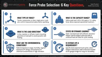
Selection starts with six concrete questions:
- What type of force? Tension, compression, shear, or multi-axis — this determines sensor geometry
- What capacity range? Define minimum and maximum expected loads, then add headroom above peak operating load
- What load direction and mounting? Inline, flange, side-mount, thru-hole, or compression-only configurations each have dedicated form factors
- Static or dynamic loading? Dynamic applications favor piezoelectric; static, long-term, or fatigue applications require strain gauge sensors with low drift
- What environment? IP rating for wet or dusty conditions, operating temperature range, and presence of strong EMI all factor into sensor selection
- What are the fatigue requirements? Any application running millions of load cycles needs a sensor explicitly rated for fatigue — not a general-purpose design
Beyond these six criteria, two factors frequently trip up engineers during spec reviews.
Off-axis and extraneous loads require careful handling. If the load path includes bending moments or lateral forces, pancake/shear web designs or multi-axis sensors reduce cross-talk error significantly compared to standard inline designs.
Signal conditioning compatibility is equally easy to overlook. Define your output requirements before finalizing sensor selection:
- Confirm whether your acquisition system expects mV/V, 4–20 mA, or a digital protocol
- Match the conditioner to the sensor before purchase — not after
- Where possible, source the sensor and conditioner together and have them calibrated as a matched system
How SensorData Technologies Can Help
SensorData Technologies, based in Shelby Township, Michigan, has been designing and manufacturing precision strain gauge force transducers, load cells, and torque sensors since 1993. Their product line spans fatigue-rated load cells, multi-axis sensors, wireless Bluetooth torque sensors, and custom turnkey measurement systems, all manufactured in-house.
Their fatigue-rated load cells are guaranteed against fatigue failure for 100 million fully reversed cycles, using SAE/AISI 4340 alloy steel selected specifically for its endurance characteristics.
That guarantee covers multiple product families: low-profile universal shear web models (5K to 500K lbs), standard shear web designs (200 to 3,000 lbs), and high-capacity universal models up to 1 million lbs.
Common questions from procurement and engineering teams:
- 100% satisfaction guarantee on all standard sensors, backed by a 60-day return policy
- Free calibration on select models for the first four years
- Competitive pricing with on-time delivery commitments
- Custom engineering with retained proprietary rights on custom designs
For applications requiring sensors beyond standard catalog offerings, SensorData's engineering team provides direct consultation to develop custom configurations, including capacity ranges, mounting geometries, and signal conditioning compatibility outside standard datasheets.
Frequently Asked Questions
What are force probes?
A force probe is a measurement device that converts applied mechanical force (tension, compression, or shear) into an electrical signal. They're used in labs, factories, and test environments to quantify force precisely, and typically form part of a larger measurement chain that includes signal conditioning and data acquisition.
What is another name for a force sensor?
Force sensors are also called force transducers, load cells, or force probes, and the terms are used interchangeably across most manufacturer catalogs. "Load cell" more commonly implies weight measurement calibration, while "force transducer" typically refers to force measured in Newtons or pounds-force.
Why must a force probe be calibrated?
Calibration corrects inherent sensor errors including zero offset, nonlinearity, hysteresis, and temperature drift. Without it, even a high-quality sensor can produce output that deviates from the true applied force. This is a particular concern in safety-critical or regulated applications.
What is the difference between a force probe and a load cell?
Structurally they're nearly identical — both typically use strain gauges and a Wheatstone bridge. The distinction is primarily in calibration and intended use: load cells are commonly calibrated in mass units (kg, lbs) for weighing applications, while force probes or force transducers are calibrated in force units (Newtons, lbf) for mechanical testing.
How do I choose the right force probe for my application?
Start by pinning down these parameters before you evaluate any sensor:
- Force type and direction (tension, compression, shear, or combined)
- Required capacity range and overload tolerance
- Static vs. dynamic or fatigue loading requirements
- Environmental conditions (temperature, humidity, vibration)
- Signal output compatibility with your data acquisition system
Getting these details clear upfront prevents both performance shortfalls and integration problems.
What industries commonly use force probes?
Force probes are used across industries where accurate measurement directly affects safety, quality, or product performance, including:
- Automotive and EV powertrain testing
- Aerospace, defense, and military applications
- Medical device manufacturing and biomedical testing
- Material, structural, and component life cycle testing
- Power generation and agricultural equipment testing