NISTIR 4823 confirms that 10 VDC is the standard bridge excitation value for strain gauge load cell calibration, with typical full-scale outputs of 2–3 mV/V. That single fact carries significant implications for system design, sensor selection, and long-term measurement reliability — all of which this guide covers in detail.
Key Takeaways
- Excitation voltage powers the Wheatstone bridge; no excitation means no output signal
- 10 VDC is the most widely used calibration and operating voltage; 5 VDC is also fully acceptable with modern electronics
- Output signal scales proportionally with excitation voltage; recalibrate if you change it or span error will follow
- Exceeding the maximum rated voltage causes self-heating, zero drift, and potential gauge damage
- Cable resistance reduces voltage before it reaches the sensor, so always verify excitation at the load cell termination point
What Excitation Voltage Represents in a Load Cell System
Excitation voltage is the DC voltage applied to the input terminals of a load cell's Wheatstone bridge. It serves as the reference power source that enables the bridge to produce a proportional millivolt output when mechanical force is applied.
How the Wheatstone Bridge Uses It
When an applied load deforms the strain gauges bonded to the load cell body, their electrical resistance changes. This unbalances the bridge, creating a voltage difference across the output terminals. That output voltage is directly proportional to two things: the magnitude of the applied force and the excitation voltage supplied.
The relationship is expressed as:
Output (mV) = Rated Sensitivity (mV/V) × Excitation Voltage (V)
So for a sensor rated at 2 mV/V at 10 VDC, full-scale output is 20 mV. At 5 VDC, it's 10 mV. The sensitivity rating in mV/V stays constant — the absolute output voltage scales with excitation.
Why This Makes Excitation an Active Variable
Excitation voltage isn't a passive property of the sensor. It governs:
- Higher excitation produces larger, easier-to-digitize output signals
- Factory calibration is performed at a specific voltage; any deviation introduces span error
- The mV/V specification is only valid at the calibration excitation level
Controlling excitation at a stable, known voltage is as critical to measurement accuracy as selecting the right sensor.
Real-World Factors That Affect Delivered Voltage
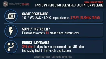
The voltage set at the instrument isn't always what reaches the bridge. Several factors cause deviation:
- A 100-foot run of #22 AWG wire has a loop resistance of approximately 3.24 ohms. In a four-wire system with multiple load cells and long cable runs, measurement errors can reach 3.752% of reading without remote sense compensation
- Fluctuations in the excitation supply produce proportional fluctuations in the output signal — a direct 1:1 error source
- Standard 350-ohm bridges draw more current than 700-ohm designs at the same excitation voltage, generating more heat and accelerating fatigue in high-cycle applications
Operating Range of Load Cell Excitation Voltage
Excitation voltage limits are defined by the manufacturer based on strain gauge design, bridge resistance, housing geometry, and application environment. Every load cell datasheet lists two distinct values: a recommended voltage and a maximum voltage.
Recommended Excitation Voltage
The two most common recommended levels are 10 VDC and 5 VDC — each appropriate depending on the application and instrumentation:
- 10 VDC is the most widely used recommended excitation for industrial strain gauge load cells. It produces a strong output signal while keeping self-heating within acceptable limits, and most factory calibrations are performed at this level. The Honeywell Model 41 low-profile load cell lists 10 VDC as its standard calibration excitation.
- 5 VDC is fully acceptable, particularly with modern instrumentation amplifiers that achieve strong signal-to-noise ratios at lower voltages. The Honeywell Model 31 miniature load cell specifies 5 VDC calibration excitation for its lower capacity ranges (50 g to 10 lb), shifting to 10 VDC only for higher ranges.
Always treat the datasheet's recommended value as the authoritative reference — not any assumed industry default.
Maximum Excitation Voltage and Safe Operating Margin
The maximum excitation voltage is the upper limit beyond which self-heating exceeds the load cell body's thermal dissipation capacity. It's an absolute boundary — not a performance target.
The self-heating numbers illustrate why this matters:
| Excitation Voltage | Power Dissipation (350-ohm bridge) | Sensitivity Impact (Low-Profile Design) |
|---|---|---|
| 5 VDC | 71 mW | +0.02% increase |
| 10 VDC | 286 mW | Baseline (calibration reference) |
| 20 VDC | 1,143 mW | −0.07% decrease |
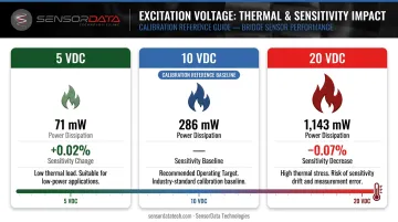
Operating at 20 VDC quadruples heat dissipation compared to 10 VDC — a significant thermal load for most load cell housings. At the other end of the range, battery-powered and wireless systems commonly use 3.3 V or 5 V to conserve power.
This is acceptable, provided the measurement system is calibrated at that same operating voltage.
Key Technical Properties of Excitation Voltage
Excitation voltage intersects with three performance parameters that create inherent trade-offs: output sensitivity, signal-to-noise ratio, and self-heating.
Sensitivity and Output Signal Magnitude
The formula is straightforward:
Signal (mV) = Rated Output (mV/V) × Excitation Voltage (V)
A 2 mV/V load cell at 10 VDC produces 20 mV full-scale. At 5 VDC, the same sensor produces 10 mV. Higher absolute output signals are easier to digitize accurately and less susceptible to noise floor interference — the primary technical argument for using higher excitation in precision or high-cycle testing environments.
The Signal-to-Noise vs. Self-Heating Trade-Off
Increasing excitation raises the output signal and improves signal-to-noise ratio. It also increases current through the resistive strain gauges, generating heat. This trade-off is most pronounced in compact load cells:
- Smaller housings have less thermal mass and reduced surface area for heat dissipation
- Compact sensors are more sensitive to excitation-induced heating than large-format, high-capacity designs
For fatigue-rated load cells like those SensorData Technologies manufactures for high-cycle testing, operating at the datasheet-specified excitation voltage isn't optional — applying a "standard" voltage borrowed from larger sensor practice introduces thermal error that compounds across millions of cycles.
Warmup Behavior and Drift
When excitation is first applied, strain gauge temperatures rise gradually until thermal equilibrium is reached. That gradual rise produces initial output drift — which is why, for critical calibrations, Interface recommends allowing load cells to stabilize at 10 VDC for up to 30 minutes before recording measurements.
Practical warmup guidelines:
- Higher excitation voltages require longer warmup periods
- Allow sufficient stabilization time before recording data in precision applications
- Build stabilization time into test protocols for high-cycle fatigue applications to maintain consistent thermal equilibrium
How Excitation Voltage Is Specified and Validated
Reading Excitation Specs from the Datasheet
Load cell datasheets list excitation voltage in the electrical specifications section — typically as both a calibration/recommended value and a maximum value. Manufacturers calibrate at the recommended voltage, so any deviation during actual use introduces a predictable span error.
ASTM E74-13a section 7.1.1.1 requires excitation voltage to be stable within 0.02% during calibration.
Section 12.4 further requires that excitation voltage amplitude, frequency, and waveform be maintained during any indicator substitution. If you swap out the signal conditioner or DAQ system, the replacement must match the original excitation conditions exactly.
SensorData Technologies includes full electrical specifications on all load cell datasheets — covering excitation parameters for standard, fatigue-rated, and multi-axis sensor designs — so engineers have the data needed to validate compatibility before installation.
Verifying Excitation at the Sensor — Not the Instrument
Always verify excitation voltage at the load cell cable termination point. Cable resistance causes voltage drop between the instrument and the sensor, and over long runs this drop can exceed acceptable thresholds.
Two solutions:
- 4-wire systems: Measure voltage at the sensor termination and account for line loss in your calibration
- 6-wire remote sense: Two additional "sense" wires allow the instrument to detect and compensate for line voltage drop, maintaining exactly the target excitation at the bridge terminals regardless of cable length
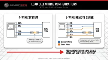
For multi-cell systems or installations with long cable runs, 6-wire configurations are the more reliable approach.
Common Misinterpretations of Excitation Voltage
Treating the Maximum as the Operating Target
Running load cells at or near maximum excitation under the assumption that "more is better" is a recurring mistake. The recommended voltage is the calibration and performance target. Operating continuously at the maximum accelerates gauge aging and thermal drift without meaningfully improving measurement quality.
Assuming Excitation Can Be Changed Without Recalibration
Output is linearly proportional to excitation. Changing from the calibration voltage to a different operating voltage introduces a fixed span error. Halving excitation from 10 VDC to 5 VDC halves the output signal — if the system's calibration data isn't updated, every reading will be systematically 50% low.
Any permanent change in operating excitation voltage requires one of two corrective steps:
- Recalibrate the system at the new operating voltage
- Verify readings against known reference loads before returning to service
ASTM E74 addresses span error from excitation changes explicitly and is the standard reference for this verification process.
Ignoring Self-Heating in Compact and Fatigue-Rated Sensors
Engineers experienced with large-format industrial load cells sometimes apply 10 VDC to compact or high-cycle fatigue-rated sensors without checking the datasheet first.
Smaller sensors with limited thermal mass may require lower excitation to maintain accuracy and structural integrity across millions of cycles. Always verify excitation limits in the datasheet before setup — sensor size alone does not determine excitation requirements.
Frequently Asked Questions
What does excitation voltage do?
Excitation voltage powers the Wheatstone bridge inside the load cell, enabling it to produce an output voltage proportional to the applied force. Without excitation applied to the bridge input terminals, no electrical output signal is generated and force measurement is not possible.
What is the recommended excitation voltage for a load cell?
Most industrial strain gauge load cells specify 10 VDC as the recommended excitation value, though 5 VDC is widely used and acceptable, particularly with modern signal conditioning electronics. Always confirm the value on the specific load cell datasheet, since compact and lower-capacity sensors sometimes specify lower ratings.
What does 2 mV/V mean?
It's the load cell's sensitivity rating: it outputs 2 millivolts per volt of excitation at full rated load. At 10 VDC excitation this means 20 mV full-scale output; at 5 VDC it means 10 mV for the same applied force. The mV/V value stays constant regardless of excitation level.
Can I use a lower excitation voltage than the manufacturer recommends?
Lower excitation is generally safe for the sensor, but the measurement system must be calibrated at that operating voltage. Running below the calibration voltage reduces output signal proportionally and introduces span error without recalibration.
How does excitation voltage affect load cell accuracy?
Unstable or incorrect excitation introduces proportional errors in the output signal, affecting span accuracy. Excessive excitation causes thermal effects, including zero drift and nonlinearity, that accumulate over time and degrade long-term measurement reliability.
Why does excitation voltage need to be stabilized?
Because output voltage is directly proportional to excitation, any supply fluctuation creates a corresponding measurement fluctuation. Regulated power supplies, signal conditioners, and DAQ systems with dedicated bridge excitation outputs all maintain the consistent supply voltage that accurate readings depend on.