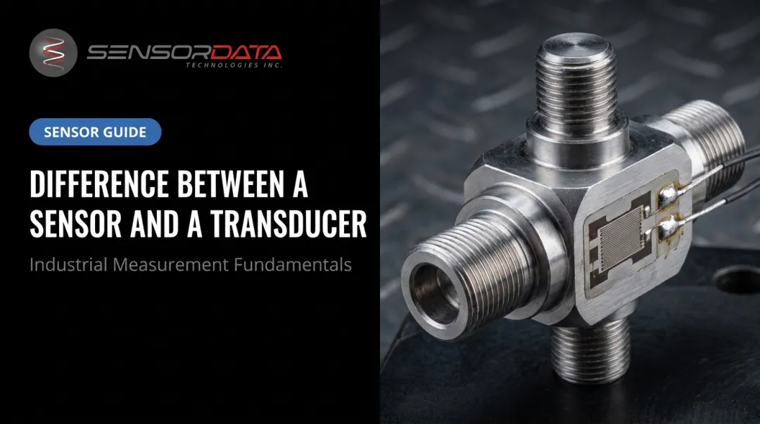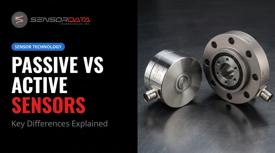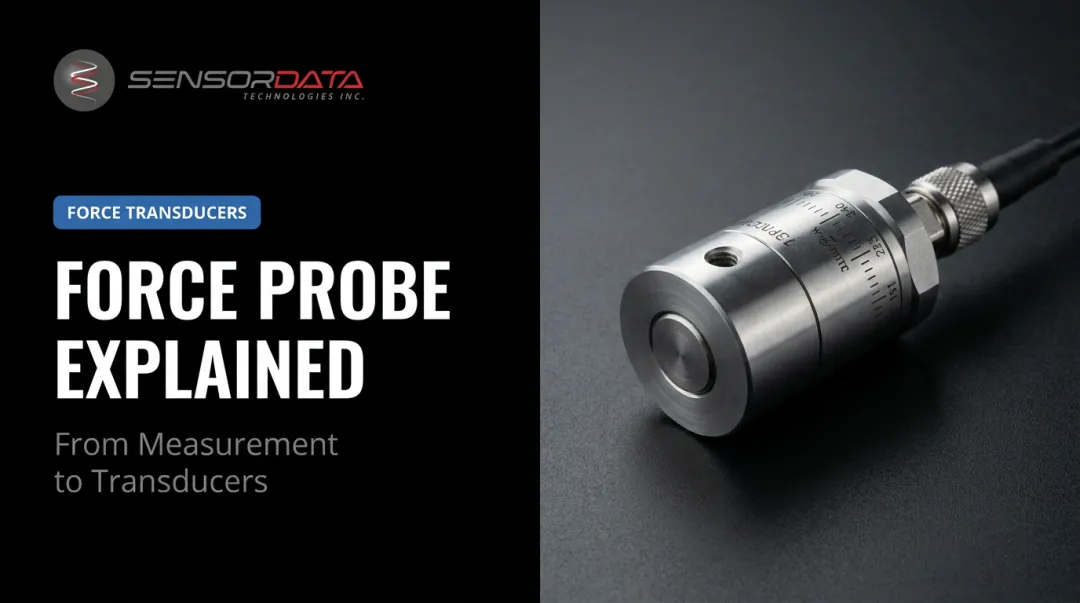
The distinction comes down to one thing: what happens to the signal. A transducer converts a physical quantity into a raw electrical signal. A transmitter takes that signal and prepares it for the real world — conditioning, amplifying, and standardizing it for transmission over long distances or direct integration with PLCs.
This article breaks down exactly how they differ, when to use each, and how to evaluate devices when manufacturers blur the line between them.
Key Takeaways
- Transducers output raw signals (typically mV/V); transmitters output standardized signals (4–20 mA, 0–10 V, or digital)
- Current-loop signals travel long distances with strong noise immunity; millivolt signals degrade over cable length
- Transducers suit precision, short-distance test environments; transmitters suit distributed industrial control systems
- These devices often work in tandem: the transducer feeds raw signal into the transmitter for conditioning and output
- Always evaluate by output specification, not device label; naming conventions overlap constantly
Transducer vs Transmitter: Quick Comparison
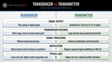
| Factor | Transducer | Transmitter |
|---|---|---|
| Signal Output | Raw mV/V or low-level voltage (e.g., 0–5 V) | Standardized 4–20 mA, 0–10 V, or digital (HART, IO-Link) |
| Transmission Distance | Short — signal degrades with cable length | Long — current signals resist noise over thousands of feet |
| Signal Processing | None built-in; compensation handled externally | Internal linearization, temperature compensation, amplification |
| Installation | Simpler wiring; requires external signal conditioning | More integrated; may require loop power supply |
| Typical Cost | Lower unit cost; external conditioning adds indirect cost | Higher unit cost; often eliminates need for separate conditioners |
Understanding the Output Boundary
According to NI, a bridge-based sensor with a 2 mV/V rated output produces just 20 mV of full-scale output at 10 V excitation. This is a real, usable signal — but it requires amplification and conditioning before it can drive most control hardware.
That conditioning gap is precisely where transmitters earn their place. Fluke identifies the 4–20 mA current loop as the most widely used process control signal, a format designed to carry measurement data reliably across long plant-floor runs without degradation.
What Is a Transducer?
A transducer is any device that converts a physical quantity — force, torque, pressure, temperature, displacement — into a proportional electrical signal. The term covers a broad category: load cells, strain gauges, piezoelectric sensors, RTDs, and thermocouples all qualify.
The operating principle is simple: the transducer senses a physical input and produces a proportional electrical output, commonly expressed in mV/V. That raw signal accurately reflects the measured quantity but requires further processing before it can drive a PLC or data acquisition system.
Four Primary Transducer Types
- Force/torque transducers (load cells, strain-gauge sensors) measure static and dynamic tensile or compressive loads; used in material testing, automotive powertrain testing, and structural load applications
- Pressure transducers convert fluid or gas pressure into a voltage signal; common in hydraulic systems, test rigs, and industrial process monitoring
- Temperature transducers (RTDs, thermocouples, thermistors) convert thermal energy into measurable electrical signals; used across manufacturing and process control
- Ultrasonic/acoustic transducers convert mechanical wave energy into electrical signals; applied in flow measurement, non-destructive testing, and level sensing
Key Operational Advantages
- High sensitivity and resolution in close-proximity measurement setups
- Minimal internal processing preserves signal fidelity — critical for high-accuracy test environments
- Fast dynamic response makes them well-suited for fatigue cycle testing, impact events, and multi-axis measurement
Use Cases for Transducers
Transducers fit naturally into test and measurement environments where the sensor sits close to the data acquisition system. Structural testing labs, material fatigue testing rigs, vehicle component testing benches, and medical device validation setups are prime examples.
SensorData Technologies' fatigue-rated load cells, including the F341–F347 series and the M231 X-Y Force Sensor, are built for exactly these environments. The M231 is rated for 100 million fully reversed cycles and designed for tire test machines measuring simultaneous radial and side forces.
Its 2 mV/V per-axis sensitivity output feeds directly into a DAQ or signal conditioner — a textbook example of a transducer serving as the precision front end in a high-cycle testing architecture.
That distinction — raw signal output handled downstream — is what separates transducers from transmitters, which package the conditioning internally.
What Is a Transmitter?
A transmitter receives an input — either from a separate sensing element or a built-in transducer — and outputs a standardized, amplified signal ready for long-distance transmission and direct connection to industrial control systems. In short, it packages transduction and signal conditioning into one device.
The Internal Signal Chain
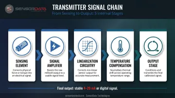
Inside a transmitter, the signal passes through:
- Sensing element — detects the physical quantity
- Signal amplifier — boosts the raw millivolt-level signal
- Linearization circuitry — corrects for non-linear sensor behavior
- Temperature compensation — adjusts for thermal drift
- Output stage — delivers a stable 4–20 mA or digital signal
That final output doesn't degrade the way a millivolt signal would over a long cable run. NI notes that current-loop signals can support cable runs of 2,000 ft or more, with wire resistance factored into the loop power supply calculation.
Why the 4–20 mA Standard Dominates
The current-loop standard offers two practical advantages that voltage signals don't:
- Noise immunity — current signals are far less affected by interference from motors, drives, and radio transmissions than voltage-based signals
- Live zero — a 4 mA signal represents a valid zero measurement; a 0 mA reading indicates a loop break, wire fault, or power loss, allowing immediate fault detection
Digital protocols extend this further. HART, for example, runs simultaneous 4–20 mA analog and digital channels over the same loop — enabling remote configuration, diagnostics, and device identification without interrupting the process signal.
When "Transducer" Labels Mislead
Many devices sold as "pressure transducers" — including products from Honeywell — include onboard signal conditioning and output a 4–20 mA signal. By function, they're transmitters. The label alone tells you nothing about the output. Always check the datasheet.
Use Cases for Transmitters
Transmitters are the right choice in:
- Large process facilities — chemical plants, power generation stations, oil and gas pipelines where sensors sit far from the control room
- Electrically noisy environments — near variable-frequency drives, large motors, or switching equipment
- Industrial automation — anywhere direct PLC integration without external signal conditioning hardware is required
The demand reflects how critical signal integrity is over distance. MarketsandMarkets projects the global pressure transmitter market will reach $3.84 billion by 2030, driven by oil and gas, chemicals, and power generation.
Transducer vs Transmitter: Which One Should You Use?
The right answer comes from four practical questions:
- How far does the signal need to travel? Short distance to a nearby DAQ → transducer. Long run across a plant floor → transmitter.
- What does your control hardware expect? PLCs with standard analog input cards want 4–20 mA. High-end DAQ systems handle mV/V directly.
- What level of dynamic response do you need? High-frequency fatigue testing and multi-axis measurement favor raw transducer outputs processed centrally.
- Where does signal conditioning happen? Centralized at DAQ → transducer. At the sensor → transmitter.
Situational Recommendations
Choose a transducer when:
- The sensor is close to a DAQ or signal conditioner
- Maximum raw signal fidelity matters — fatigue cycles, multi-axis force/torque, impact testing
- You have existing signal conditioning infrastructure (like SensorData's Model I200 AC Strain Gage Conditioner, which accepts mV/V inputs and optionally outputs 4–20 mA)
Choose a transmitter when:
- The sensor is far from the control system
- The environment has significant electrical noise
- Direct plug-and-play compatibility with a PLC is required
The "Both Together" Architecture
In many industrial systems, especially large-scale process control, a transducer serves as the precision front end and its output feeds into a separate transmitter for conditioning and long-distance delivery. This layered approach (transducer → signal conditioner → transmitter) is common wherever both measurement accuracy and remote monitoring are required.
SensorData's signal conditioning ecosystem follows this model:
- I200 AC Strain Gage Conditioner — accepts raw mV/V inputs from torque and force transducers; outputs standard ±5 VDC or optional 4–20 mA for downstream integration
- i400 Telemetry Module — extends the chain further with wireless transmission up to one mile line-of-sight
The Practical Rule on Terminology
Look at the output specification in the datasheet:
- mV/V or low-level voltage output → functioning as a transducer
- 4–20 mA or amplified 0–10 V output → functioning as a transmitter
Conclusion
Neither transducer nor transmitter is universally better. The right device depends on where it sits in the measurement chain, how far the signal must travel, and what the control system expects as input.
Transducers deliver precision and fast dynamic response for close-proximity setups. Transmitters deliver noise-immune, standardized signals for distributed industrial systems. Get it wrong, and you're looking at signal degradation, installation rework, and measurement data you can't trust.
For force, torque, and load measurement in high-cycle fatigue testing, automotive powertrain testing, or multi-axis measurement, SensorData Technologies has over 30 years of custom-engineered transducer design experience. The engineering team can help match the right measurement architecture to your application. Contact SensorData Technologies at (586) 739-4254 or Sales@SensorDataTech.com to discuss your requirements.
Frequently Asked Questions
What are the 4 types of transducers?
The four main types are force/torque (load cells, strain gauges), pressure, temperature (RTDs, thermocouples, thermistors), and ultrasonic/acoustic transducers. Each converts a different physical quantity — mechanical load, fluid pressure, thermal energy, or sound waves — into a proportional electrical signal.
Are transducer and transformer the same?
No. A transducer converts a physical quantity (force, pressure, heat) into an electrical signal. A transformer is an electrical device that transfers energy between circuits by changing voltage or current levels through electromagnetic induction; it never interacts with physical process variables.
What is the difference between a transducer and a transceiver?
A transducer converts physical energy into an electrical signal in one direction only. A transceiver is a combined transmitter-receiver device that both sends and receives signals, commonly used in communication systems like radios, Ethernet switches, and fiber optic networks.
Can a transducer work without a transmitter?
Yes. When the sensor is close to a signal conditioner or DAQ system, a standalone transducer works fine, since the DAQ handles amplification and processing. For long-distance transmission or direct PLC integration, a transmitter is typically needed to standardize and amplify the raw signal.
What is the difference between a sensor and a transducer?
"Sensor" is the broader term for any device that detects a physical stimulus. A transducer specifically converts that stimulus from one energy form into an electrical signal. All transducers are sensors, but not all sensors qualify as transducers; some simply detect without converting to a different energy form.
Which is more accurate, a transducer or a transmitter?
Accuracy depends on the application, not the device type. In close-proximity setups with external signal conditioning, transducers can deliver very high resolution. Transmitters add internal processing that may introduce minor variations, so for high-precision dynamic testing, a quality transducer with dedicated external conditioning typically delivers better results.