Introduction
Most mechanical failures don't happen without warning. They build slowly — through overloads, misalignment, torsional resonance, or gradual component wear — and the organizations that catch these signals early are the ones that avoid costly downtime and rework.
Torque is one of the most informative signals in any rotating mechanical system, yet it remains one of the least monitored. A machine running under abnormal torque conditions doesn't always trip an alarm or shut down immediately. It just wears faster, fails sooner, and costs more.
According to Siemens' True Cost of Downtime 2024 report, unplanned downtime costs the world's 500 largest manufacturers $1.4 trillion annually — roughly 11% of revenues. For automotive plants specifically, that figure reaches $2.3 million per hour.
What follows is a practical reference for engineers and maintenance professionals — covering sensor selection, calibration, and the common mistakes that undermine even well-designed monitoring programs.
Key Takeaways
- Torque monitoring measures rotational force on shafts, fasteners, and mechanical assemblies to detect overloads and anomalies before failures occur
- Dynamic measurement captures transient events — shock loads and torsional vibrations — that static measurement cannot
- Sensor selection hinges on capacity, accuracy class, mechanical configuration, and environmental conditions
- Calibration, proper mounting, and signal conditioning directly determine data reliability
- Pairing torque data with vibration and temperature readings exposes root causes that isolated measurements miss
What Is Torque Monitoring and Why Does It Matter?
Torque is the rotational force that drives shafts, gears, and mechanical assemblies. The relationship between torque, power, and speed is direct: as the Engineering ToolBox defines it, rotating power equals torque multiplied by angular velocity (P = T × ω).
A practical example: a motor-gearbox drive train on a bucket elevator runs at a predictable torque under normal load. Add wet material, a blocked discharge, or a worn gear set, and the torque demand changes — sometimes dramatically. Without measurement, that change is invisible until something breaks.
Torque monitoring is the ongoing measurement and analysis of torque values in mechanical systems to understand real-time operational demands, detect anomalies, and prevent failures.
It operates within the broader framework of condition monitoring, where torque readings combine with vibration, temperature, and oil quality data to build a complete picture of machine health. Think of it the way a physician uses multiple diagnostics: no single test tells the whole story.
The Cost of Ignoring It
Unmonitored torque leads to predictable consequences:
- Broken gear teeth from sustained overloads
- Shaft fatigue fractures from torsional vibration
- Premature coupling failure from oscillating loads
- Accelerated bearing wear from misaligned or overloaded drive trains
These aren't rare edge cases. A documented example from a Megger Baker/Transcat case study identified a broken end bell on a 1,250 HP circulating water pump through instantaneous torque analysis — a defect that would have caused five weeks of reduced output. Catching it early saved $3.92 million.
Causes range from design flaws and incorrect machine operation to load conditions that exceed original design parameters. The common thread: torque anomalies typically appear before failure, often by enough time to intervene — but only if you're measuring in the first place.
How Torque Is Measured: Static vs. Dynamic Methods
Static Torque Measurement
Take a torque wrench verifying a fastener after tightening — that's static measurement in its most familiar form. It checks torque after a process is complete, confirming the outcome.
This approach answers a simple question — "Was the right torque applied?" — but it cannot reveal what happened during the process. A fastener can reach target torque while cross-threaded, with a missing gasket, or with excessive friction masking inadequate clamp load. Static checks confirm outcomes, not process quality.
Dynamic Torque Measurement
Dynamic measurement captures torque continuously during an active process. That continuous view is what separates reactive inspection from genuine process control.
During machine start-up, a drive train may experience torque spikes two to three times the nominal operating value. During steady-state operation, torsional resonance can create cyclical stress invisible to static checks.
Southwest Research Institute documents how torsional natural frequencies in drivetrain systems can cause damage when critical speeds coincide with excitation frequencies. This is a failure mode detectable only through dynamic measurement.
The Core Measurement Technology
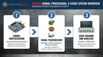
Both approaches rely on the same underlying principle: strain gauges bonded to a shaft that twists under torsional load. Four gauges configured in a Wheatstone bridge circuit convert mechanical deformation into a proportional millivolt signal. That signal is then:
- Amplified by signal conditioning electronics
- Transmitted from the rotating shaft (via slip rings, rotary transformers, or wireless telemetry)
- Logged and analyzed by a data acquisition system
Torque-and-Angle Monitoring
Torque value alone tells you how much force was applied. Add rotational angle, and you can see how the joint behaved throughout the entire tightening sequence. According to Atlas Copco, monitoring both parameters simultaneously can detect missing gaskets, cross-threaded fasteners, material defects, and operator errors, reducing rework and warranty claims in assembly environments.
The torque-angle curve shape reveals what the torque value alone cannot. A fastener that reaches target torque after too few degrees of rotation may have bottomed out. One that takes too many degrees may be cross-threaded. In both cases, the joint appears acceptable on a single torque reading — making angle monitoring essential for assembly process validation.
Types of Torque Sensors and Transducers
Choosing the wrong sensor type is one of the most common implementation mistakes. The two fundamental categories serve distinct purposes.
Rotary (In-Line) Torque Transducers
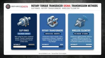
Rotary transducers rotate with the shaft during operation, making them the correct choice for continuous, in-process torque measurement on motors, gearboxes, and drive trains. Signal transmission options include:
- Slip rings: direct electrical contact, best for lower-speed applications with accessible maintenance schedules
- Rotary transformers (magnetic coupling): contactless signal transmission with lower maintenance demands and higher speed capability
- Wireless telemetry: no physical connection or cabling required — the practical choice for difficult-to-access or remote rotating shafts
Each transmission method suits different speed ranges, access constraints, and facility environments. SensorData Technologies manufactures rotary torque transducers across all three, including the BT4000 series (Bluetooth wireless, up to 100-foot range, induction-powered rotor) and the SYNTH series (wireless transmission exceeding 500 feet, rated for ZONE 1 DIV 1 explosive environments). Both use 16-bit digital signal conversion for noise immunity in demanding industrial settings.
Reaction Torque Transducers
Reaction transducers remain stationary, making them ideal for static and quasi-static applications:
- Torque wrench calibration
- Fastener testing and audit
- Bench-top test stand applications
- Process equipment with minimal shaft rotation
Like rotary sensors, reaction transducers use strain gauge Wheatstone bridge technology — but the mechanical interface is designed to resist rotation rather than rotate freely.
Key Selection Criteria
| Parameter | What to Evaluate |
|---|---|
| Rated capacity | Must cover peak dynamic torque, not just nominal operating torque |
| Accuracy class | DIN 51309 classifies sensors from 0.05 to class 5 — match to application requirements |
| Mechanical configuration | Shaft, flange, square drive, or hollow flange — determined by the machine interface |
| Environmental conditions | Temperature range, humidity, exposure to contaminants or explosive atmospheres |
For demanding applications — fatigue testing, life cycle testing, or continuous industrial monitoring — fatigue-rated sensor designs are critical. SensorData Technologies designs and manufactures custom torque transducers specifically for these conditions, with overload protection ratings typically reaching 150% of full scale or higher depending on the application.
Best Practices for Implementing Torque Monitoring
Sensor Selection and Placement
Size for peak torque, not average torque. A conveyor motor may run at 200 Nm under steady load, but see 600 Nm during start-up or a sudden jam. A sensor selected for 250 Nm will fail — or at minimum, produce corrupted data — when that spike hits.
As Interface notes, undersizing based on average torque can cause permanent sensor failure. Always account for transient loads from acceleration, impacts, and process upsets.
Placement guidance:
- Position sensors at the point of highest diagnostic interest (typically gearbox output shaft or coupling)
- Ensure accessibility for maintenance and future calibration without full disassembly
- Consider the full mechanical interface — side loads, thrust, and bending moments can introduce measurement error if the sensor isn't protected from them
Mounting, Cabling, and Signal Conditioning
Mechanical installation quality directly determines measurement quality:
- Rigid mounting eliminates mechanical play that introduces noise into the signal
- Coupling alignment on inline rotary installations prevents extraneous bending loads on the sensor body
- Cable routing should separate signal cables from power cables to minimize electromagnetic interference
Signal conditioning requirements for a complete measurement chain:
- Bridge excitation voltage supply
- Amplification of the raw millivolt output
- Filtering to remove electrical noise (hardware anti-aliasing filters are preferred over software-only filtering)
- Compatible DAQ system for logging, display, and analysis
Calibration and Ongoing Maintenance
Calibration underpins every other monitoring decision. Without it, you're reading numbers without knowing what they mean.
Torque sensors drift over time due to:
- Mechanical wear from continuous use
- Temperature cycling effects on the strain gauge adhesive and bridge balance
- Overload events that permanently shift the zero reference
- Aging of the sensor materials
FUTEK recommends annual recalibration as a baseline, with immediate recalibration after severe shock events, temperature extremes, or before any critical test. PCB echoes the same guidance: annually as a rule of thumb, and proactively after known overload conditions.
For quality audits and regulated industries, traceable calibration records are equally important — they demonstrate measurement integrity and support process control requirements.
Combining Torque with Complementary Parameters
Torque data in isolation has limits. A spike at start-up looks different from a spike during steady operation. A gradual torque increase over weeks means something different than a sudden step change.
ISO 17359:2018 — the standard governing condition monitoring and diagnostics — recommends correlating multiple parameters to establish failure mode signatures:
- Torque
- Vibration
- Temperature
- Rotational speed
- Process flow rates
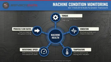
Synchronous multi-channel analysis that aligns torque data with vibration and speed measurements is the most reliable way to distinguish a developing mechanical fault from a normal process variation.
Torque Monitoring Across Industries
Automotive and Manufacturing
Assembly line fastener tightening is one of the highest-volume torque monitoring applications. Torque-and-angle monitoring during fastener tightening catches defects that torque-only inspection misses, including cross-threaded fasteners, shallow holes, and missing gaskets.
Quality Magazine notes that friction consumes 80% to 90% of applied tightening torque — meaning only 10% to 20% actually generates clamp load. Small deviations in friction coefficient produce large variations in actual joint clamping force at a given torque target. Angle data helps compensate for this.
For engine test benches and drivetrain analysis, continuous dynamic torque measurement characterizes performance maps, identifies resonance conditions, and validates powertrain designs before production release.
Industrial and Heavy Machinery
Several industries share a common vulnerability: extended operation under varying loads on shafts and gearboxes that are difficult to access and expensive to replace. This applies across:
- Cement plants running continuous kiln drives
- Marine propulsion systems with limited shaft access
- Power generation turbines and gearboxes
- Mining conveyors operating under variable load cycles
A documented case from Binsfeld illustrates what continuous monitoring can prevent: 4,500 HP crude-oil pumping units were experiencing repeated elastomeric coupling failures. Strain gauge torque telemetry identified torsional oscillations above 984 RPM as the root cause. Limiting operation to 970 RPM eliminated the failures entirely — no hardware replacement required.
Permanent online torque monitoring enables this kind of targeted intervention. Operators address the specific condition causing damage rather than replacing components on a schedule or after the fact.
Aerospace and Material Testing
Aerospace applications demand measurement precision that standard industrial sensors cannot provide. Hinge fatigue testing, structural load characterization, and component life cycle testing require sensors that maintain accuracy across millions of load cycles in environments with extreme temperature ranges and vibration.
That same precision carries into materials characterization work. Testing for shear modulus, yield strength, and ductility under torsional loading depends entirely on sensor accuracy for valid results. Instron describes torsion testing as fundamental to evaluating how materials and devices behave under angular displacement — used in R&D programs across aerospace, defense, and advanced materials development.
Common Torque Monitoring Mistakes to Avoid
Even well-designed monitoring programs can produce unreliable results when these three pitfalls go unaddressed.
Sizing the Sensor Incorrectly
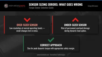
Both directions create problems:
- Over-sized sensors lose resolution at normal operating levels — small changes become indistinguishable from noise
- Under-sized sensors risk permanent overload damage during dynamic load spikes
Always size for peak dynamic torque with appropriate margin, not nominal operating torque.
Neglecting Calibration Schedules
Deferred calibration is one of the most common ways monitoring programs fail quietly. A sensor that has drifted 3% from its baseline still displays readings — those readings get logged, trended, and acted on, but they're wrong. Early warning signals get missed, or false alarms erode confidence in the program entirely.
Reading Torque Without Context
A sudden torque spike during start-up is normal. The same spike during steady-state operation at rated speed is a warning. Without context — speed, load state, vibration, process conditions — the same data point leads to completely different conclusions.
The most effective monitoring programs treat torque as one channel in a multi-parameter analysis, cross-referenced against operating conditions rather than evaluated alone.
Frequently Asked Questions
What is a torque monitor?
A torque monitor is a measurement system that combines a torque sensor or transducer, signal conditioning equipment, and data acquisition instrumentation to measure, display, and record rotational force on a mechanical component. Most systems deliver real-time readout alongside data logging for trend analysis and alarm management.
What is the difference between static and dynamic torque measurement?
Static torque measurement checks torque after a process is complete — such as verifying a tightened fastener with a torque wrench. Dynamic torque measurement continuously captures torque during an active process, detecting transient events like shock loads, start-up spikes, and torsional vibrations that static checks cannot see.
How much does a torque sensor cost?
Standard reaction torque transducers from manufacturers like Transducer Techniques range from approximately $875 to $3,200 depending on capacity and configuration. High-accuracy inline rotary transducers start around $9,000 and up. Custom-engineered or fatigue-rated sensors are typically priced on application — contact SensorData Technologies for a quote based on your specific requirements.
What is the 20/80 rule for torque?
The 20/80 rule is a fastener tightening guideline: apply roughly 20% of the target torque first (snug torque) to seat joint members, then bring fasteners to the final target value. This staged approach ensures consistent clamp load distribution and reduces joint scatter across the assembly.
How often should torque sensors be calibrated?
Annual recalibration is the standard baseline for most applications. High-cycle use, harsh environments, or any known overload event warrants shorter intervals — and always recalibrate before critical tests or after exceeding a sensor's rated capacity.
What industries benefit most from torque monitoring?
Automotive, aerospace, power generation, marine, mining, industrial manufacturing, and material testing all benefit directly. Any industry relying on rotating machinery or precision fastening can reduce unplanned downtime, improve assembly quality, and extend the service life of critical assets through consistent torque monitoring.