The good news: most load cell failures follow predictable patterns. Overloading, moisture ingress, wiring faults, and mechanical misalignment account for the majority of field problems — and all of them respond well to systematic diagnosis.
This guide covers the five most common load cell failure modes, a four-step troubleshooting process grounded in verified manufacturer diagnostic procedures, and a clear framework for deciding whether a unit is worth repairing or needs replacing.
Key Takeaways
- The five most common failures — erratic output, zero drift, dead signal, reversed readings, and overload damage — each have a distinct diagnostic signature.
- A standard multimeter and visual inspection can isolate most faults before you involve a repair facility.
- Follow mechanical → electrical → signal order; skipping ahead masks the real problem.
- A computed zero offset above 20% of rated output confirms permanent overload damage — recalibration will not fix it.
- For newer or under-warranty units, contact the manufacturer before discarding — free repair or replacement may be available.
What Is a Load Cell?
A load cell is an electromechanical transducer that converts an applied force into a proportional electrical signal. Most strain gauge load cells use a Wheatstone bridge: four strain gauges bonded to a machined flexural element. When force is applied, the flexure deforms slightly, changing gauge resistance and unbalancing the bridge. The result is a millivolt output proportional to both the applied load and the excitation voltage — expressed as a sensitivity rating in mV/V.
That output is only as reliable as the components producing it. Several common conditions degrade accuracy over time:
- Repeated loading cycles — fatigue the flexure and weaken gauge bonds
- Temperature cycling — shifts zero balance and affects gauge factor
- Moisture exposure — corrodes connections and compromises insulation resistance
- Overloading — permanently deforms the flexure, skewing calibration
Understanding these failure modes is the foundation of effective troubleshooting.
Common Load Cell Problems
Most failures announce themselves through a specific symptom. Matching the symptom to its likely cause cuts diagnosis time.
Erratic or Unstable Readings
Symptoms: Display values fluctuate under constant load, readings spike without changes to applied force, or the output won't settle.
Likely causes:
- Moisture ingress into the load cell body or junction box — Interface identifies low insulation resistance as a primary driver of unstable output
- Loose or broken solder connections in the cable or connector
- Electromagnetic interference from nearby motors, drives, or welding equipment
- Ground loops created by multiple grounding points in the signal circuit
Zero Drift or Inability to Return to Zero
Symptoms: Display reads non-zero with no load applied, zero drifts gradually during a test run, or the scale can't be tared consistently.
Likely causes:
- Temperature-induced resistance changes — even compensated cells drift outside their rated temperature window
- Excitation voltage instability at the indicator or power supply
- Mechanical overload causing permanent flexure deformation (addressed in detail below)
No Output or Dead Signal
Symptoms: Display reads zero regardless of applied load; no response when load is added or removed.
Likely causes:
- Broken excitation lead or severed signal wire
- Incorrect wiring — excitation and signal leads transposed
- Open or shorted strain gauge leg collapsing the bridge
- Excitation voltage not reaching the load cell terminals (check at the cell, not the indicator)
Negative or Reversed Reading
Symptoms: Indicator shows a negative value when a positive load is applied, or output moves opposite to the expected direction.
Likely causes:
- Signal leads wired in reverse (positive and negative signal conductors swapped)
- Load cell installed in wrong orientation — tension cell used in compression, or vice versa
- Load applied off-axis relative to the cell's rated load direction
Overload Damage
Symptoms: Readings change unpredictably, zero balance has shifted dramatically from the original documented value, or output won't return to baseline after load removal.
Likely causes: Loading beyond rated capacity — from a sudden shock load or sustained overloading — causes permanent plastic deformation in the flexural element.
Interface's load cell troubleshooting documentation provides clear thresholds for assessing damage severity:
| Zero Offset (% of Rated Output) | Interpretation |
|---|---|
| Within ±1% | Normal — healthy cell |
| 10% to 20% | Probable overload damage |
| Above 20% | Permanent deformation confirmed |
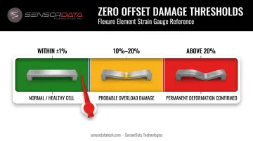
Any reading outside the ±1% baseline warrants further investigation before returning the cell to service.
How to Troubleshoot a Load Cell Step-by-Step
Work in sequence: mechanical inspection first, then electrical, then live signal. Ruling out physical and wiring issues before reaching for a multimeter keeps the diagnostic path clean and prevents a secondary problem from masking the root cause.
Step 1: Visual and Mechanical Inspection
Start here before touching a multimeter.
- Inspect the load cell body for cracks, corrosion, surface deformation, or signs of impact
- Check mounting surfaces for flatness, cleanliness, and correct alignment — a cocked or eccentric mount introduces parasitic side loading that directly corrupts output
- Examine the cable for cuts, kinking near the connector, damaged insulation, or pulled strain relief
- Confirm mounting hardware is torqued to the manufacturer's specification
- Verify there is exactly one load path running through the load axis — multiple load paths introduce errors the cell's signal cannot account for
Mechanical problems are the most common root cause in field failures — and the cheapest to resolve before any electrical work begins.
Step 2: Check Electrical Connections and Excitation Voltage
With the cell disconnected from the indicator:
- Inspect all junction box terminals for corrosion, loose connections, or mis-wired color codes
- Reconnect and verify the excitation voltage at the load cell terminals — not just at the indicator output. Interface specifies 10 VDC as the preferred excitation for factory-calibrated units, though acceptable ranges vary by model (HBK H35, for example, accepts 5–15 VDC)
- Measure insulation resistance between all conductors tied together and the cable shield, then to the load cell body. Rice Lake's EZ Test guidance lists below 1,000 MΩ as a potential problem and below 200–300 MΩ as a definite problem; Interface sets its own threshold at 5,000 MΩ. Always reference your manufacturer's datasheet for the applicable limit. Low insulation resistance almost always indicates moisture ingress or pinched wiring.
Step 3: Measure Bridge Resistance and Zero Balance
Use an ohmmeter with at least 0.1-ohm resolution.
Measure bridge input resistance (across excitation leads) and output resistance (across signal leads). For a standard 350-ohm bridge, Interface specifies 350 ± 3.5 ohms as the acceptable range for both
Measure the four individual bridge leg resistances — all combinations of adjacent lead pairs (RAB, RBC, RCD, RAD)
Calculate computed unbalance using the Interface formula:
Unbalance (mV/V) = 1.4 × (RAC − RAB + RBD − RCD)
Calculate zero offset percentage:
Zero Offset % = 100 × Unbalance ÷ Rated Output
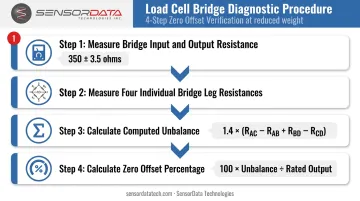
Compare the zero offset result against these thresholds:
| Zero Offset % | Interpretation |
|---|---|
| 10–20% | Probable overload — inspect for mechanical damage |
| Above 20% | Overload confirmed — cell likely requires replacement |
Step 4: Live Signal Output Test
Once resistance and zero balance values fall within spec, move to live signal testing. With excitation applied and no load on the cell, record the baseline millivolt output. Then:
- Apply a known calibrated weight and measure the output
- Compare measured output against the expected value: Expected mV = Sensitivity (mV/V) × Excitation (V) × (Applied Load ÷ Rated Capacity)
- Step the load up incrementally to verify linearity across the range
- Remove load and confirm the output returns to baseline
Non-linearity, signal noise, or a baseline that doesn't recover after unloading all indicate internal damage that won't be corrected by recalibration.
When to Repair vs. Replace Your Load Cell
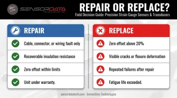
The fix-or-replace decision comes down to whether the problem is in the external components or the load cell's structural core.
Repair When:
- The fault is in the cable, connector, junction box terminal, or wiring — no structural damage to the cell body or flexure
- Insulation resistance is recoverable after drying and moisture is addressed
- Zero offset is within acceptable limits and recalibration can restore the unit to manufacturer specifications
- The unit may still be under warranty — SensorData Technologies offers free repair service or replacement parts at their discretion for qualifying units, so contact them before discarding
Replace When:
- Bridge resistance calculations confirm the computed zero offset exceeds 20% of rated output. Permanent plastic deformation has occurred, meaning electrical re-zeroing will not restore structural integrity or measurement performance
- Physical inspection reveals cracks, visible flexure deformation, or corrosion that has penetrated the cell body
- The unit has repeatedly failed the same diagnostic tests after repair — at that point, the continued repair cost exceeds replacement value
- The application involves high-cycle loading and the cell has reached or exceeded its rated fatigue life — fatigue-rated load cells guaranteed for 100 million fully reversed cycles are a better long-term investment than repeatedly repairing a standard cell
Preventive Measures to Extend Load Cell Service Life
Most load cell failures are preventable. A consistent maintenance routine costs far less than unplanned downtime or bad data.
Key preventive actions:
- Inspect cables, connectors, mounting hardware, and the cell body at regular intervals matched to your duty cycle — catch corrosion and wear before they compound
- Stay within rated capacity; add mechanical overload stops on shock-prone systems; keep mounting surfaces clean, flat, and properly torqued to eliminate parasitic side loading
- Record baseline resistance and zero balance values at installation, then recalibrate on a set schedule — a 12-month interval is the widely accepted industry starting point, adjusted for application demands
- Ask your manufacturer about calibration support — SensorData Technologies offers free calibration on select models for a defined period, which makes it easier to build a formal maintenance schedule from day one
Frequently Asked Questions
How do I know if my load cell is damaged or just needs recalibration?
Calibration errors produce consistent, repeatable offset or sensitivity drift. Damage shows up as erratic readings, inability to return to zero, or abnormal bridge resistance values. Run the bridge resistance and zero balance checks in Step 3 — if the computed zero offset is above 10% of rated output, the problem is likely structural, not a calibration shift.
How do I test a load cell with a multimeter?
A multimeter measures bridge input and output resistance, individual leg resistances for the zero offset calculation, and insulation resistance to the shield and body. It also captures live millivolt output under a known load. Compare every reading against the manufacturer's datasheet values — deviations from nominal resistance or low insulation readings point directly to the fault category.
What causes a load cell to give no output or read zero under load?
The most common causes are a broken excitation lead, an open or shorted strain gauge leg, incorrect wiring, or excitation voltage that isn't reaching the cell terminals. Start by confirming excitation voltage at the load cell input — not at the indicator — before working backward through the wiring.
Can a load cell be repaired after overload damage?
No. Overloading causes permanent plastic deformation in the flexural element. Electrical re-zeroing adjusts the displayed output but does nothing for the physical structure or performance parameters. Once bridge calculations confirm definitive overload (zero offset above 20%), replacement is the right call.
What is zero drift in a load cell and how do I fix it?
Zero drift is a gradual change in no-load output over time, caused by temperature changes, excitation voltage instability, or mechanical creep. Check excitation stability first, verify thermal compensation is within the cell's rated range, then recalibrate. If drift persists, check insulation resistance — moisture ingress closely mimics temperature-related drift.
How often should a load cell be inspected or calibrated?
As a baseline, calibrate annually or after any event that may have caused overloading or physical damage. High-cycle and harsh-environment applications need more frequent checks. Follow the manufacturer's recommended schedule and document baseline readings at each interval to track drift over time.