Calibration is the correction mechanism. But it's not as straightforward as zeroing a scale. The accuracy of your result depends on your reference standard, environmental conditions during the procedure, and how precisely you set zero and span. A poorly calibrated transducer can read within what looks like an acceptable range while still introducing enough error to compromise process integrity.
This guide covers everything you need: pre-calibration preparation, a clear step-by-step procedure, the physical variables that affect accuracy, common mistakes, recalibration timing, and troubleshooting guidance for the problems technicians encounter most often.
Key Takeaways
- Calibration compares a transducer's output to a known reference standard, then corrects zero and span to eliminate deviation
- The reference standard must meet the 4:1 Test Uncertainty Ratio (TUR) — four times more accurate than the device under test
- Always document As-Found data before making any adjustments
- Record As-Left data after calibration — both entries are required for a traceable calibration certificate
- Temperature, linearity, hysteresis, and installation conditions most commonly compromise calibration accuracy
- Most industrial pressure transducers require recalibration every 90 to 365 days, depending on application risk and historical drift data
What You Need Before Calibrating a Pressure Transducer
Preparation determines calibration quality more than the procedure itself. Skipping pre-checks produces calibrations that look correct in the lab but fail in service — a costly mistake in any precision measurement environment.
Equipment and Reference Standard Requirements
You'll need the following before applying a single psi of test pressure:
- Calibrated reference pressure standard — a deadweight tester for lab-grade primary standard work, or a digital/handheld pressure calibrator for field use
- Regulated pressure source — a hand pump or electronic pressure controller capable of stable, repeatable output
- Connection tubing and fittings rated above the maximum test pressure
- Multimeter or loop calibrator to measure electrical output (voltage or current)
- Transducer specification sheet with expected output values at each test point
The most important equipment decision is your reference standard. According to NIST, the 4:1 TUR rule — adopted in MIL-STD-45662A in 1988 and incorporated into ANSI/NCSL Z540-1 in 1994 — requires the reference standard to be at minimum four times more accurate than the device under test.
If your transducer has a stated accuracy of ±0.5% full scale, your reference must be ±0.125% or better. A calibrator that doesn't meet this ratio makes it impossible to reliably confirm whether the transducer is within specification.
Deadweight testers serve as primary pressure standards — they generate pressure from a known force applied over a known area and offer the highest accuracy. Digital pressure calibrators are secondary standards, calibrated against primary standards, and are appropriate for most field and bench work when their uncertainty meets the TUR requirement.
Transducer Documentation and Pre-Checks
Before connecting anything, gather the transducer's original specification sheet and any prior calibration records. These tell you the expected output at zero and full-scale pressure, the compensated temperature range, and the manufacturer's accuracy specification — all of which you need to evaluate As-Found data meaningfully.
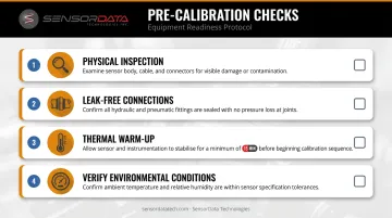
With documentation in hand, complete these physical pre-checks before starting:
- Inspect the transducer body and port for physical damage, corrosion, or contamination
- Confirm all fittings and connections are leak-free at the test pressure range
- Power the transducer on and allow it to reach thermal equilibrium — consult the manufacturer's warm-up specification (one precision transducer manual, the WIKA CPT6020, specifies 15 minutes)
- Verify that ambient temperature and humidity fall within the transducer's specified operating limits
How to Calibrate a Pressure Transducer: Step-by-Step
The standard procedure follows three phases: As-Found test, zero and span adjustment, and As-Left verification. Do not skip or reorder them.
Step 1: Set Up the Reference Standard and Connect the Transducer
Connect both the transducer under test and the reference standard to a common pressure source using a T-fitting or manifold. Both devices must see the same applied pressure simultaneously. Any pressure drop between them introduces error that you cannot separate from transducer error.
Safety checks before pressurizing:
- Confirm all tubing and fittings are rated above the maximum test pressure
- Verify the pressure source is regulated and cannot overpressure the system
- If the transducer is mounted at a different elevation than the reference port, calculate the fluid column head correction. Fluke notes that even air or nitrogen introduces approximately 0.0003% of reading per inch of elevation difference, which matters at high-accuracy calibration levels
Step 2: Apply Loop Power and Verify Electrical Output
Supply the correct excitation: typically 24 VDC for 4–20 mA output transducers. Before applying any pressure, confirm the transducer produces a readable output signal at the expected baseline value (4 mA for a standard 4–20 mA device at zero pressure).
If the baseline reading deviates from the expected value, record it. This is your first As-Found data point. Do not adjust it yet.
Step 3: Perform the As-Found Test
With the setup confirmed and stable, apply pressure at three points minimum: 0%, 50%, and 100% of the full-scale range. At each point, record:
- The reference standard's pressure reading
- The transducer's actual electrical output
- Ambient temperature at time of test
This is the As-Found data: the transducer's condition before any adjustment. Mensor defines As-Found as the instrument condition upon arrival at calibration.
This data is required under ISO/IEC 17025 for traceable calibration certificates. It tells you whether the transducer was in or out of tolerance before you touched it, which matters for audits, interval decisions, and root cause analysis.
Step 4: Adjust Zero and Span
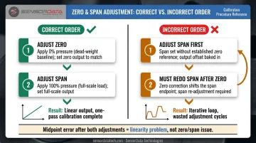
Zero adjustment first — always. With the pressure source fully vented to the reference (0% of range), adjust the zero trim until the output matches the expected minimum value (4 mA for a 4–20 mA device). This corrects the offset at the minimum pressure point.
Span adjustment second. With pressure at 100% of full scale, adjust span until the output matches the expected full-scale value (20 mA). Span correction changes the slope of the output line.
Two important limits to understand:
- Adjusting span before zero forces a second span correction after zero is set, creating an iterative loop that wastes time and risks pushing calibration out of tolerance
- Zero and span adjustment only correct the endpoints. If the midpoint (50%) still shows error after both adjustments, that's a linearity problem, requiring multipoint linearization, not additional zero/span trimming
Step 5: Perform the As-Left Test and Document Results
Repeat the same three-point ascending pressure test after adjustment. If all points fall within the acceptable tolerance band specified in the transducer's datasheet, you're done with the adjustment phase. If any point exceeds tolerance, repeat Steps 4 and 5.
Once all points are within specification, document both data sets in a calibration certificate that includes:
| Certificate Element | Required Content |
|---|---|
| Instrument description | Model, manufacturer, serial number |
| Reference standard | Identification, traceability, uncertainty |
| Date of calibration | Actual calibration date |
| Environmental conditions | Temperature, humidity at time of test |
| As-Found data table | Readings at each test point before adjustment |
| As-Left data table | Readings at each test point after adjustment |
| Technician signature | Name and qualification |
Key Parameters That Affect Calibration Accuracy
Correct procedure alone doesn't guarantee accurate results. Several physical and environmental variables can introduce errors that mimic transducer failures — knowing them helps you isolate the actual source.
Temperature Effects
Temperature causes sensor materials to expand or contract, shifting zero output and span. As Ashcroft explains, even stable ambient temperature changes can create zero and span offsets by altering sensor element behavior.
Most transducers are compensated over a defined temperature range. Operating outside it accelerates drift and widens uncertainty. Calibrate within that range when possible. If lab temperature differs significantly from the installation environment, apply a temperature correction factor or shorten the calibration interval.
Reference Standard Accuracy and Traceability
Your calibration is only as valid as your reference standard. NIST defines metrological traceability as an unbroken chain of calibrations, each with documented uncertainty, connecting your working instrument back to a national or international measurement institute.
In practice, that chain looks like this:
- NMI/primary realization (NIST or equivalent)
- Primary pressure standard (deadweight tester)
- Secondary/transfer calibrator (digital pressure calibrator)
- Working transducer (the device under test)
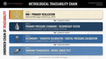
A reference standard without documented NIST or equivalent NMI traceability cannot generate a compliant calibration certificate for regulated industries.
Linearity and Hysteresis
Setra notes that pressure transducer accuracy is calculated from non-linearity, hysteresis, and non-repeatability combined. These are distinct from zero/span errors:
- Non-linearity: the transducer's output doesn't shift proportionally across the range, so midpoint errors persist even after zero and span are corrected
- Hysteresis: readings taken while increasing pressure differ from readings at the same point while decreasing pressure
If midpoint errors exceed specification after zero/span adjustment, your options are multipoint software linearization (if the transducer's interface supports it) or replacement.
Environmental and Installation Conditions
Field calibrations carry more uncertainty than lab calibrations. Contributors include:
- Vibration from nearby machinery
- Electromagnetic interference affecting signal integrity
- Head height differences between the reference port and transducer (fluid column pressure adds or subtracts from applied pressure)
- Temperature swings during the calibration procedure itself
Quantify these contributors in your uncertainty budget. An error that appears in a field calibration may be environmental, not the transducer. Making adjustments without identifying the root cause compounds the problem.
Common Mistakes When Calibrating a Pressure Transducer
Even experienced technicians make these mistakes — and most are easy to avoid once you know what to look for.
Skipping the warm-up period. A transducer that hasn't reached thermal equilibrium will show zero and span errors that disappear once it warms up in service. Calibrating cold produces a certificate that's accurate on paper and wrong in the field.
Skipping As-Found documentation. Without As-Found data, you can't determine whether the transducer was in tolerance before you adjusted it. That gap removes audit trail integrity and makes calibration interval optimization impossible.
Using a reference standard that doesn't meet the 4:1 TUR. If your calibrator is only twice as accurate as the transducer, the combined uncertainty band may exceed the transducer's rated accuracy — making it impossible to confirm the device is within spec.
Adjusting span before zero. Span is calculated relative to the zero baseline. Correct zero first, then adjust span. Reverse that order and you've shifted the span endpoint, which means starting over.
Ignoring environmental factors during field calibration. Calibrating near vibrating equipment, in direct sunlight, or during a temperature swing introduces noise and thermal drift. You end up measuring environmental error, not transducer error.
When and How Often to Recalibrate
Recalibration frequency depends on manufacturer recommendations, application criticality, operating environment, and what your As-Found history actually shows.
Manufacturer and Standards-Based Intervals
Mensor states that pressure calibration intervals are typically 90 to 365 days, determined statistically from prior calibration results. Manufacturers specify these intervals to represent a confidence level — commonly 95% — that the device will remain within specification over that period.
Industries regulated under ISO/IEC 17025 or equivalent standards must document and adhere to their stated intervals. That said, ISO/IEC 17025 prescribes no specific numbers for pressure transducers; it requires documented, justified intervals.
Condition-Based Recalibration Triggers
Regardless of your scheduled interval, recalibrate immediately if any of the following occur:
- The transducer was exposed to pressure beyond its rated range
- It was dropped or subjected to mechanical shock
- Readings appear inconsistent with known process conditions
- The device was repaired or returned from service
- As-Found data from the last calibration showed the device significantly out of tolerance
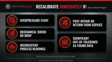
Historical As-Found data is the most actionable input for interval optimization. If a transducer consistently arrives at calibration still within tolerance, the interval can often be extended. If it routinely drifts, shorten it.
Troubleshooting Common Calibration Problems
Output Drift Returns Quickly After Calibration
Recurring drift usually means the transducer has been operating outside its compensated temperature range, exposed to pressure spikes beyond its rating, or subjected to vibration that fatigues the sensing element. Calibration corrects the current reading but doesn't address the root cause.
To diagnose:
- Review whether operating pressure regularly approached or exceeded the rated range
- Confirm operating temperature falls within the compensated range listed in the datasheet
- If drift recurs within a shortened interval, replace the transducer — recalibrating it won't hold
Unable to Achieve Zero at Low-Pressure End
This usually means the pressure source isn't fully vented, leaving residual pressure in the system. It can also indicate the zero trim range is too narrow to correct an internal offset caused by diaphragm damage or severe mechanical drift.
To diagnose:
- Vent the pressure source completely and confirm the transducer is at true ambient/reference pressure before zeroing
- Check for fluid blockages in the pressure port
- If zeroing falls outside the adjustment range, the internal offset exceeds what trimming can fix — the transducer requires manufacturer evaluation, not further adjustment
Nonlinear Output Across the Pressure Range
A curved response typically develops from sensing element fatigue, pressure port contamination, or gradual sensor degradation. Zero and span adjustments cannot fix midpoint errors — they only shift the endpoints.
To diagnose:
- Run a full ascending and descending multi-point test (0%, 25%, 50%, 75%, 100%, then back down) to map where nonlinearity is worst
- If midpoint errors exceed specification, check whether the transducer supports multipoint software linearization through its interface
- If linearization isn't available, return the unit for manufacturer evaluation or replace it
Frequently Asked Questions
Do transducers need to be calibrated?
Yes. Transducer output drifts over time due to mechanical stress, temperature cycling, and component aging. Without periodic calibration, measurement error accumulates until readings no longer reflect actual pressure — which can compromise safety systems, process control, and quality records.
What are the three types of calibration?
Three calibration types cover most industrial applications:
- Laboratory calibration uses primary standards like deadweight testers for highest accuracy and full traceability
- Bench calibration uses secondary standards in a controlled shop environment
- Field calibration uses portable digital calibrators for on-site verification with minimal downtime
How often should a pressure transducer be calibrated?
Most manufacturers specify intervals of 90 to 365 days depending on sensor type and accuracy class. High-criticality applications typically require shorter intervals. Historical As-Found data from previous calibrations is the most reliable input for extending or shortening intervals based on observed drift.
What is zero and span adjustment in pressure transducer calibration?
Zero adjustment corrects the output error at minimum pressure (the low end of the range). Span adjustment corrects the error at full-scale pressure. Zero must always be adjusted before span, since span correction is calculated relative to the zero baseline.
What is As-Found and As-Left data in pressure transducer calibration?
As-Found data records the transducer's output before any adjustment is made. As-Left data records its output after adjustments are complete. ISO/IEC 17025 requires both on traceable calibration certificates, and together they reveal drift trends across calibration cycles.
What tools do you need to calibrate a pressure transducer?
Core equipment includes:
- Reference pressure standard — deadweight tester or digital calibrator meeting the 4:1 TUR
- Regulated pressure source — typically a hand pump
- Rated tubing and fittings compatible with your pressure range
- Multimeter or loop calibrator to measure electrical output
- Transducer specification sheet for reference values and tolerances