Introduction
In automotive crash testing, aerospace structural validation, and medical device development, a measurement error of just a few microvolts can compromise safety conclusions or invalidate months of testing. The tolerance for that kind of error is effectively zero.
Digital load cells address this directly. By converting the analog signal to a numerical value inside the sensor , before it ever travels through a cable, they eliminate the most common sources of measurement error in traditional systems.
Research from HBM shows how exposed analog signals are: with a standard 2 mV/V sensitivity and 5V excitation, only 10 mV reaches the amplifier input — and a 0.1 N resolution step can represent just 10 µV at that level. That signal is genuinely difficult to protect over long cable runs in industrial environments.
This article covers what a digital load cell is, how it works, how it compares to analog, the main types available, key advantages, common applications, and what to evaluate when selecting one.
Key Takeaways
- Digital load cells convert the analog signal to digital at the source, eliminating cable-induced interference
- Digital load cells outperform analog systems in noise immunity, temperature stability, and maintenance simplicity
- Strain gauge, piezoelectric, and capacitive designs each suit distinct load ranges and environments
- Selection depends on load capacity, IP rating, communication protocol, and supplier support quality
- Automotive, aerospace, medical, and material testing all rely on digital load cells for mission-critical data
What Is a Digital Load Cell and How Does It Work?
A digital load cell is a force-measuring sensor with an integrated analog-to-digital converter (ADC) and microprocessor. Unlike a conventional analog load cell, it delivers a processed numerical output directly — no external signal conditioning required.
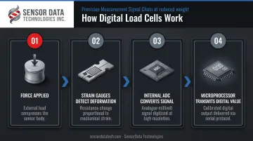
The Four-Step Measurement Process
- Applied force deforms the sensor's mechanical structure, causing the elastic element to flex under load
- Bonded strain gauges detect the deformation — resistance changes generate a small analog voltage
- The internal ADC converts that voltage to a digital signal entirely within the sensor housing
- A built-in microprocessor then processes, calibrates, and transmits the final value numerically to the indicator or control system
Key Internal Components
| Component | Function |
|---|---|
| Strain gauges | Primary sensing elements |
| ADC | Converts analog voltage to digital |
| Microprocessor | Processes, calibrates, and outputs data |
| Temperature sensor | Enables automatic compensation |
| Communication interface | Outputs data to indicators, PLCs, or software |
The digital output travels via serial communication — commonly RS-485 using Modbus-RTU protocol. The indicator receives an actual weight or force value, not raw voltage.
Performing A/D conversion inside the sensor keeps the vulnerable low-level analog signal confined to micrometers of travel, not meters. The long cable run carries a robust digital signal instead, which delivers three practical advantages:
- Resistance to electromagnetic interference from motors, drives, and nearby equipment
- Elimination of temperature-induced drift over long cable runs
- No signal degradation from voltage drop across cable resistance
Digital Load Cell vs. Analog Load Cell: Key Differences
The core difference is where signal conversion happens.
Analog load cells output a raw millivolt-per-volt (mV/V) signal to an external indicator that performs the A/D conversion. Digital load cells output a pre-processed numerical value — the indicator receives data, not voltage.
Three Error Sources Analog Systems Introduce
- Cable-induced noise — at µV to mV signal levels, even minor electromagnetic interference corrupts the reading
- Temperature drift — the cable, indicator, and load cell each drift independently under temperature changes
- Component variability — replacing a cable or indicator in an analog system typically requires full recalibration with test weights
HBM's analysis quantifies the cable problem directly: a four-wire analog circuit loses 0.36% sensitivity over just 5 meters and 3.6% over 50 meters due to wire resistance alone. In long-cable installations, that's a meaningful accuracy penalty.
Noise Immunity
Digital signals operate at several volts — not microvolts. That voltage differential makes digital output far more resistant to radio frequency interference, electromagnetic fields, and the noise generated by motors, drives, and other industrial equipment.
Maintenance and Calibration
Any component replacement in an analog system often triggers a full recalibration cycle. Digital load cells store calibration data internally, so the indicator can be replaced without complete scale recalibration — the load cell retains its calibration parameters in onboard memory, according to B-TEK's CPD-M documentation.
This matters most in facilities where downtime is expensive. Swapping an indicator doesn't mean pulling test weights back out.
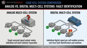
Multi-Cell Diagnostics
In analog multi-cell systems, a junction box with resistor trimming balances outputs across cells. If one cell drifts or fails, identifying which one requires systematic troubleshooting.
Digital systems give each cell its own independent signal path. The indicator can identify exactly which cell is underperforming, a diagnostic step that analog junction-box systems cannot perform directly.
Types of Digital Load Cells
Strain Gauge Digital Load Cells
The most widely used type. A metal element (steel, aluminum, or alloy) with bonded strain gauges changes resistance as it deforms under load. In a digital load cell, that resistance change is digitized on-board.
Best suited for:
- General industrial weighing
- Platform scales and hopper systems
- OEM machinery with static and dynamic loads
- Component life cycle testing
Strain gauge load cells cover the broadest range of capacities and form factors, making them the default choice for most industrial measurement applications.
Piezoelectric Digital Load Cells
Piezoelectric load cells generate an electric charge from crystalline materials (typically quartz) when mechanical stress is applied. As PCB Piezotronics documents, they excel at dynamic and quasi-static force events including impact, impulse, and compression.
Best suited for:
- Crash and impact testing
- Vibration analysis
- High-speed dynamic force measurement
One important limitation: if a static force is applied continuously, the electrostatic charge output gradually leaks back to zero. Piezoelectric sensors are not suitable for static or continuous weighing without additional charge amplifier analysis.
Capacitive Digital Load Cells
Capacitive load cells measure load by detecting the change in capacitance between two conductive plates as force shifts their separation. TE Connectivity notes they offer high resolution and sensitivity — but also high sensitivity to temperature and humidity. Controlled environments around 25°C are often specified.
Best suited for:
- Laboratory precision measurement
- Controlled industrial processes requiring very fine resolution
- Pharmaceutical and chemical process weighing where accuracy tolerances are tight
Fatigue-Rated Digital Load Cells
For applications involving repeated cyclical loading, standard load cells are not enough. Fatigue testing, automotive endurance testing, and aerospace structural testing subject sensors to millions of load reversals — conditions that cause ordinary load cells to fail prematurely.
Best suited for:
- Automotive and powertrain endurance testing
- Aerospace structural and component testing
- Material fatigue and life cycle testing
SensorData Technologies engineers fatigue-rated load cells guaranteed against fatigue failure for 100 million fully reversed load cycles, making them a direct fit for the most demanding cyclic test environments.
Key Advantages of Digital Load Cells
Accuracy and Measurement Stability
Built-in temperature compensation and high internal resolution eliminate the analog transmission errors that cause drift in traditional systems. The result is measurably stable readings across varying operating conditions. Some models list combined error specifications of ≤ ±0.017% FS, with:
- Output resolution of 256,000 to 512,000 raw-count increments at full load
- A/D conversion rates up to 1,200 updates per second
Direct System Integration
That signal precision carries forward into how digital load cells connect to the rest of your infrastructure. They communicate directly with PLCs, SCADA systems, data loggers, and cloud platforms via standard industrial protocols — no additional signal conditioning hardware required. Common protocols include:
- RS-485/Modbus-RTU
- CANbus and CANopen
- Profibus
Built-In Diagnostics
The independent per-cell signal output also pays off in maintenance. Each cell can be monitored individually, so indicators flag a fault immediately rather than requiring manual troubleshooting across an entire array. Self-monitoring of supply voltage and internal temperature reduces unplanned downtime and lowers lifecycle maintenance costs — particularly in multi-cell installations where analog systems offer no equivalent visibility.
Common Applications Across Industries
Digital load cells appear wherever measurement accuracy, noise immunity, and data integration matter simultaneously.
| Industry | Typical Applications |
|---|---|
| Automotive | Component fatigue testing, tire uniformity grading, clutch force measurement |
| Aerospace | Airframe structural load testing, multi-component R&D, thrust measurement |
| Medical devices | Surgical instrument force control, rehabilitation equipment |
| Agriculture | Onboard weighing systems, grain handling |
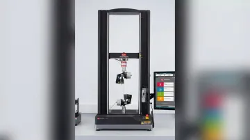
| Material testing | Tensile/compression machines, cyclic endurance testing |
| Power generation / petroleum | Cable tension monitoring, process vessel weighing |
SensorData Technologies has deployed sensors across several of these sectors directly — custom multi-component sensors for Boeing 777X R&D, structural load testing up to 2,400 kN for BAM-certified bridge truss work, and fatigue-rated sensors for tire uniformity testing in cyclic endurance environments.
As applications grow more complex, multi-axis digital load cells take this further — measuring force in multiple directions simultaneously and feeding that data directly into automated control systems for robotics and advanced manufacturing.
How to Choose the Right Digital Load Cell
Capacity, Range, and Environmental Rating
Match the load cell's rated capacity to the peak load in your application, with appropriate safety factor. Anyload's load cell specifications guidance notes safe overload examples of 150% of full scale — confirm ultimate overload limits from the specific datasheet.
For environmental protection, IEC 60529 defines the IP rating system. Common load cell ratings include:
- IP65 — dust-tight, protected against water jets
- IP67 — dust-tight, submersion to 1 meter
- IP68 — continuous submersion (depth per manufacturer specification)
- IP69K — high-pressure washdown
Always verify the exact IP rating on the product datasheet, not the rating system description alone.
Communication Protocol and System Compatibility
Confirm the load cell's output protocol matches your existing indicator, PLC, or data acquisition system. Common options include:
- RS-485 with Modbus-RTU (most common)
- CANbus / CANopen
- Profibus
- ASCII serial
Digital load cells and indicators from different manufacturers are not always interchangeable — verify compatibility at the protocol, baud rate, and physical layer level before specifying hardware.
Supplier Expertise and Support
The right supplier provides more than catalog products. For demanding or non-standard applications, look for:
- In-house design and manufacturing capability
- Calibration services (NIST-traceable)
- Engineering consultation for custom requirements
- Clear warranty terms and documented performance guarantees
SensorData Technologies (Shelby Township, MI) manufactures precision force and torque sensors in-house, with engineering support for custom designs and NIST-traceable calibration services. For non-standard applications — unusual form factors, extreme fatigue cycle requirements, or multi-axis measurement — working directly with the manufacturer eliminates the middleman and compresses development timelines.
Frequently Asked Questions
What is a digital load cell?
A digital load cell is a force or weight sensor with an integrated ADC and microprocessor that converts the measurement to a digital signal internally. It delivers a numerical output directly to an indicator or control system — no external signal conditioning needed.
What is the difference between analog and digital load cells?
The key difference is where signal conversion occurs. Analog load cells output raw millivolt voltage that the indicator converts, making them vulnerable to cable noise and temperature drift. Digital load cells convert internally, producing cleaner, more stable output with lower susceptibility to environmental interference.
What are the main types of load cells?
The four most commonly referenced types are:
- Strain gauge — resistance-based, the most common
- Piezoelectric — dynamic force measurement via charge generation
- Capacitive — high resolution via capacitance change
- Hydraulic/pneumatic — fluid pressure-based, heavy industrial use
Digital versions of the first three are most prevalent today.
What communication protocols do digital load cells use?
Most commonly RS-485 with Modbus-RTU. Some models support CANbus, CANopen, Profibus, or ASCII serial communication, depending on the manufacturer and application. Always match the protocol to your existing system before purchasing.
Are digital load cells compatible with analog indicators?
No — digital load cells require compatible digital indicators. Even among digital systems, load cells and indicators from different manufacturers can be incompatible due to proprietary specifications. Verify compatibility at both the protocol and hardware level before specifying.
When should you choose digital over analog?
Digital is the better choice when:
- Cable runs are long or environments are electrically noisy
- You need to monitor multiple cells independently
- Integration with PLCs or data acquisition systems is required
Analog remains simpler and cost-effective for short-run, low-noise, single-cell setups.