This guide is written for controls engineers, instrumentation technicians, and automation teams with working knowledge of analog signal handling and PLC programming. Inexperienced personnel risk incorrect scaling, ground loops, or sensor damage that's difficult to trace after commissioning.
What follows covers the complete integration sequence: understanding load cell signal requirements, selecting the right connection method, wiring, PLC configuration, calibration, and validation — following accepted industry practice throughout.
Key Takeaways
- A raw load cell cannot connect directly to a PLC — a signal conditioner is always required to amplify the millivolt output and supply excitation voltage.
- 4-20mA output is preferred over 0-10VDC in industrial environments due to noise immunity and broken-wire detection.
- Integration follows six steps in order: signal conditioning, wiring, PLC input configuration, scaling logic, calibration, and validation.
- Common failure points: reversed signal wires, incorrect scaling formulas, single-ended shield grounding errors, and skipped calibration.
- Load cell selection — matched to your application's rated capacity and cycle requirements — determines the accuracy of everything that follows.
Understanding Load Cell Signal Requirements and Connection Options
Why You Can't Skip Signal Conditioning
Load cells output a differential millivolt signal proportional to applied force. Per HBM's technical guidance, a 2 mV/V load cell produces just 10 mV at 5V excitation — far below the input range of any standard PLC analog module. Connecting a raw load cell directly to a PLC input is not a workaround; it simply doesn't work.
A signal conditioner serves three functions:
- Supplies excitation voltage to the load cell (typically 5VDC or 10VDC)
- Amplifies the mV-level output to a PLC-compatible signal range
- Provides filtering to reduce electrical noise
No integration is possible without this intermediate device.
Analog Output Options: 4-20mA vs. 0-10VDC
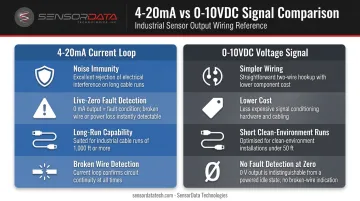
Most signal conditioners offer two analog output types. The choice matters depending on your installation environment.
| Output Type | Best For | Key Advantage |
|---|---|---|
| 4-20mA | Industrial environments, longer cable runs | Noise immunity; live-zero fault detection |
| 0-10VDC | Short runs in clean electrical environments | Simpler wiring, lower cost |
The 4-20mA standard uses 4mA as live zero, meaning 0mA indicates a loop fault — broken wire or power loss — rather than a valid zero reading. As Fluke explains, this allows a PLC to distinguish a true zero-load condition from a wiring failure. In industrial automation, that distinction is operationally significant.
Digital and Fieldbus Options
More advanced load cell transmitters support digital communication protocols, including:
- Modbus RTU (RS-485)
- EtherNet/IP
- Profibus DP
- Profinet IO
- DeviceNet and EtherCAT
Digital connection is worth the additional setup complexity when you need multi-sensor networks, remote tare/calibration control from the PLC, or when the plant already runs a specific fieldbus. The LAUMAS TLB transmitter series, for example, supports RS-485 Modbus RTU through EtherCAT across a single product family — illustrating how broad fieldbus coverage has become at the transmitter level.
Matching the Load Cell to the Signal Conditioner
Before integration begins, verify these load cell specifications against the signal conditioner's input range:
- Rated capacity
- Sensitivity (mV/V)
- Excitation voltage requirement
- Number of wires (4-wire vs. 6-wire)
- IP/environmental rating
For demanding industrial applications — fatigue testing, material testing machines, or high-cycle automation — the load cell's suitability for dynamic loading is equally critical. SensorData Technologies manufactures fatigue-rated and precision load cells designed for applications where consistent long-term signal accuracy is required.
That product line carries a 100 million fully reversed cycle guarantee backed by AISI 4340 alloy steel construction. That specification matters when the load cell is operating inside a PLC-controlled closed-loop system cycling continuously over months.
Load Cell to PLC Integration Guide
Integration follows a defined sequence. Skipping any stage produces accuracy or stability problems that are difficult to isolate once the system is live.
Prerequisites and Compatibility Checks
Confirm load cell specifications:
- Rated capacity, sensitivity (mV/V), excitation voltage
- 4-wire vs. 6-wire configuration
- IP rating relative to the installation environment
Verify PLC analog input module type:
- Voltage input (0-10VDC) vs. current input (4-20mA)
- Input resolution — 12-bit or 16-bit significantly affects measurement precision
- Whether the PLC supports a dedicated load cell/weight module
If the PLC supports one, dedicated weight modules are worth the investment. The Siemens SIWAREX WP321 and Hardy HI 1756, for example, offer substantially higher resolution (the SIWAREX WP321 provides ±2 million parts resolution), built-in 4-wire/6-wire support, and automatic calibration without reference weights. Generic analog input cards require more manual scaling and offer less diagnostic capability.
Required conditions before installation:
- Confirm electrical isolation from high-power circuits
- Plan cable routes away from motor drives, VFDs, and high-current conductors
- Verify PLC resolution is adequate for required measurement accuracy
Required Tools and Components
- Load cell (capacity and sensitivity matched to application)
- Signal conditioner or amplifier (matched to load cell output range)
- Shielded twisted-pair cable
- 24VDC power supply
- PLC with compatible analog input module or dedicated weight module
- Terminal blocks
- Multimeter for pre-power verification
Use shielded cable for the load cell-to-amplifier segment without exception. Ground the shield at the signal conditioner end only — grounding both ends creates a ground loop that introduces the noise you're trying to eliminate.
How to Wire and Configure a Load Cell to a PLC
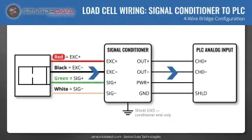
Standard 4-wire load cell wiring:
| Wire Color (Common) | Function | Connects To |
|---|---|---|
| Red | Excitation+ | Amplifier EXC+ |
| Black | Excitation- | Amplifier EXC- |
| Green | Signal+ | Amplifier SIG+ |
| White | Signal- | Amplifier SIG- |
Note: wire colors vary by manufacturer. Always verify against the load cell's calibration data sheet — not assumed color conventions.
For 6-wire load cells, connect Sense+ and Sense- to the amplifier's sense terminals. These leads allow the amplifier to compensate for excitation voltage drop across long cable runs, which can otherwise cause measurable sensitivity loss.
Signal conditioner output setup:
- Configure output type (4-20mA or 0-10VDC) to match the PLC input module
- Set zero point — no-load output (e.g., 4mA at zero load for 4-20mA output)
- Set full-scale output — rated capacity output (e.g., 20mA at rated load)
PLC-side configuration:
Configure the analog input channel to match signal type and range, then write a scaling formula to convert raw analog counts to engineering units. The standard linear scaling equation:
Weight = ((raw_input - zero_count) / (span_count - zero_count)) × rated_capacity
In Structured Text, a basic implementation looks like:
// Scale 4-20mA input (0-32767 counts) to 0-5000 lbs
zero_count := 6554;   // counts at 4mA (zero load)
span_count := 32767;  // counts at 20mA (full load)
rated_capacity := 5000.0;

weight_lbs := ((REAL(raw_AI_input) - zero_count) / (span_count - zero_count)) * rated_capacity;
Rockwell's analog scaling documentation uses the same low/high signal to low/high engineering unit mapping — the formula is consistent across platforms, though register names vary by PLC manufacturer.
With wiring and scaling configured, the next step is verifying the system reads correctly under known conditions.
Post-Integration Calibration and Validation
Two-point calibration procedure:
- Zero point: With no load applied, confirm the amplifier output matches the expected zero value (4mA for 4-20mA output). Record or adjust the zero offset in the PLC.
- Span point: Apply a known traceable reference load at or near rated capacity. Confirm the output matches the expected full-scale value. Adjust span in the signal conditioner if needed.
Once both points are set, save calibration data to the signal conditioner's non-volatile memory (EEPROM). Power cycling a system with calibration stored only in volatile memory resets it — a common source of post-outage measurement errors.
Validation checks before commissioning:
- Stable no-load readings over a 5-minute period (no drift)
- PLC engineering unit values match the known applied load within acceptable tolerance
- Clean signal — no oscillation or noise spikes visible in the PLC data monitor
- Broken-wire alarm triggers correctly (if using 4-20mA)
Common Load Cell to PLC Integration Problems and Fixes
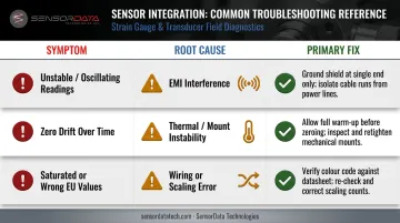
The three most common integration failures each have a distinct signature in the PLC display — and a direct cause-and-fix path. Use this table to quickly identify which issue applies, then follow the detail below.
| Symptom | Root Cause | Primary Fix |
|---|---|---|
| Unstable/oscillating values | EMI from VFDs; shield ground loop | Single-end shield ground; separate conduit |
| Zero drift over time | Thermal resistance shift; loose mounting | Warm-up before zeroing; check mechanical mounts |
| Saturated or wrong EU values | Swapped signal wires; bad scaling | Verify color code; re-check zero/span counts |
Noisy or Fluctuating Readings
The PLC displays unstable, oscillating values under a static load. The usual culprit is electrical interference from nearby VFDs or power conductors coupling into load cell signal wiring. This is compounded by improper shield grounding — grounding both ends of the cable shield creates a ground loop that amplifies the noise it's meant to block.
To resolve it:
- Use shielded twisted-pair cable; ground the shield at the signal conditioner end only
- Route load cell wiring in a separate conduit, away from power conductors
- Enable the signal conditioner's built-in digital filtering
Zero Drift Over Time
The PLC reading gradually shifts from zero with no load applied, or the zero point changes after temperature variations. Three causes are common:
- Thermal resistance changes in the load cell or amplifier
- Loose mechanical connections creating unintended preload on the sensor
- Zeroing performed before the system has fully warmed up
Allow the system to warm up per the load cell datasheet minimum before zeroing. Inspect all mechanical mounting points for looseness or binding, and verify that temperature compensation is enabled on the amplifier — or enable auto-zero tracking if available.
Saturated or Incorrect Engineering Unit Readings
The PLC displays a value pegged at the top or bottom of range regardless of actual load, or the displayed values don't match the applied force. Likely causes:
- Reversed signal wires (SIG+ and SIG- swapped)
- Incorrect scaling formula inputs (zero count or span count)
- Load cell overload from mechanical shock or undersized capacity selection
Verify wiring against the load cell's color code and amplifier terminal markings. Re-check zero count and span count values using the live PLC data monitor at zero load and full load. If overload is suspected, inspect the load cell body for deformation and replace if damaged.
Pro Tips for a Successful Load Cell to PLC Integration
These four practices address the most common failure points engineers encounter when commissioning and maintaining load cell to PLC systems.
Use 4-20mA for any industrial cable run. Current signals tolerate wiring resistance within loop power limits and resist induced voltage noise better than voltage signals. In environments with VFDs, motor drives, or general electrical noise, 4-20mA is the practical default — not just the cautious choice.
Use what dedicated weight modules actually offer. When specifying a dedicated load cell module over a generic analog card, take advantage of auto-calibration, tare/zero commands via ladder logic, overload detection, and high-resolution measurement. The Siemens SIWAREX WP321's ±2 million part resolution and calibration without reference weights represent a meaningful step up from a manually scaled 12-bit analog input.
Document every calibration. Record the date, reference load used, raw count values at zero and span, and the technician who performed it. Store this alongside the PLC project file. When a measurement drifts six months after commissioning, that record is what makes diagnosis possible.
Specify fatigue-rated load cells for high-cycle applications. In fatigue testing rigs, material testing machines, or hydraulic actuator systems running PLC-controlled load cycles, a standard load cell will degrade prematurely and fail without a clear warning signal. SensorData Technologies' fatigue-rated load cells are engineered for 100 million fully reversed cycles using AISI 4340 alloy steel and shear web construction, available from 5K to 500K pound capacities — the right specification for any dynamic application where measurement accuracy has to hold through months of continuous cycling.

Conclusion
Successful load cell to PLC integration depends on executing each stage correctly — matched load cell and signal conditioner, disciplined wiring, accurate scaling, and documented calibration. Errors at any step compound. A reversed signal wire or an incorrectly entered span count produces readings that look plausible until someone applies a known reference load and finds the numbers don't match.
Treat calibration as an ongoing maintenance activity. Re-calibrate after any mechanical disturbance to the load cell mounting, after significant temperature changes, or on a defined schedule appropriate to the application's accuracy requirements.
When measurement accuracy directly affects process quality — as it does in automotive, aerospace, and material testing — the manufacturer's application support is a practical resource, not just a last resort. SensorData Technologies manufactures precision and fatigue-rated load cells with over 25 years of application engineering experience, and works with engineers on both standard configurations and custom integration requirements.
Frequently Asked Questions
What is a load cell in PLC?
In a PLC context, a load cell is a force transducer connected to the PLC via a signal conditioner to provide real-time force or weight data as an analog or digital input. The PLC uses this data for process monitoring, control logic, or setpoint-based automation.
What are the 4 types of PLCs?
The four main types are modular, compact, rack-mounted, and nano/micro PLCs. For load cell integration, modular PLCs are most flexible — they accept dedicated analog or weight input modules that offer higher resolution and built-in calibration functions compared to compact or micro PLC analog options.
Can you connect a load cell directly to a PLC without a signal conditioner?
No. A raw load cell outputs a millivolt-level signal — typically 2-3 mV/V — that falls well below the input range of standard PLC analog modules. A signal conditioner is always required to amplify the signal to a compatible range (4-20mA or 0-10VDC) and to supply the excitation voltage the load cell needs to operate.
What is the difference between analog and digital load cell to PLC connection?
Analog connection (4-20mA or 0-10VDC) is simpler and suits single-sensor applications with basic monitoring requirements. Digital/fieldbus connection (Modbus RTU, EtherNet/IP, Profibus) enables multi-sensor networks, remote configuration, and PLC control of tare and calibration functions — though initial setup and configuration time is higher.
How do you calibrate a load cell connected to a PLC?
Two-point calibration: zero the reference with no load applied, then apply a known traceable load near rated capacity to set the span. Adjust scaling values in the PLC and/or signal conditioner until the displayed value matches the reference load, then save settings to non-volatile memory.
What causes noisy or unstable readings in a load cell PLC system?
The most common causes are electrical interference from nearby VFDs or power cabling, inadequate cable shielding, and ground loops from grounding the shield at both ends. Use shielded twisted-pair cable with single-point grounding at the signal conditioner, route signal cables away from power lines, and apply signal conditioner filter settings to attenuate residual noise.