Both sensor types have genuine strengths. The problem is that most comparisons oversimplify the tradeoffs in ways that don't hold up in demanding applications like automotive suspension testing, aerospace structural validation, or material fatigue analysis. This article breaks down how each type works, where each performs best, and how to make the right call for your specific application.
Key Takeaways
- Analog sensors output continuous electrical signals — ideal for high-fidelity, real-time force, torque, and strain measurement
- Digital sensors convert measurements to binary values, offering better noise immunity and simpler integration with PLCs and SCADA systems
- Analog sensors require external signal conditioning hardware; digital sensors handle this onboard
- Many precision test systems combine both — analog sensors with high-resolution external DAQ hardware
- Let application demands drive the choice, not sensor type familiarity
Analog vs. Digital Sensors: Quick Comparison
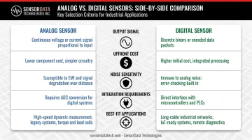
The table below summarizes the key differences across the criteria that matter most in industrial measurement applications.
| Aspect | Analog Sensor | Digital Sensor |
|---|---|---|
| Output Signal | Continuous voltage or current (0–10V, 4–20mA, mV/V) | Discrete binary values (0s and 1s) |
| Upfront Cost | Generally lower component cost | Higher — onboard ADC, microcontroller, comms hardware |
| Noise Sensitivity | Susceptible to EMI and RFI | Higher noise immunity, especially over long cable runs |
| Integration | Requires ADC and signal conditioning for digital systems | Direct interface with PLCs, microcontrollers, DAQ systems |
| Best For | High-fidelity, real-time continuous measurement (force, strain, torque) | Networked systems, long-distance transmission, automated data logging |
What Are Analog Sensors?
An analog sensor measures a physical quantity and produces a continuous electrical signal (voltage or current) that varies in direct proportion to the measured parameter. Unlike digital systems, there's no discretization step. Every nuance of a changing input, such as a load building gradually across a fatigue cycle, is captured without quantization loss.
How Analog Sensors Work
The operating principle depends on the physical phenomenon being exploited. Strain gauge-based load cells use piezoresistance — the resistance of bonded foil changes as the sensing element deforms under load. Thermocouples use the Seebeck effect to produce a millivolt-level output proportional to temperature. Piezoelectric sensors generate charge under mechanical stress.
Common output formats include:
- mV/V — standard bridge output for strain gauge load cells and force transducers (typically 2–3 mV/V rated output)
- 0–10V or 1–5V — amplified voltage outputs for short cable runs in low-noise environments
- 4–20mA current loop — the most widely used process-control signal for longer transmission distances, with a live-zero at 4mA that distinguishes valid zero readings from broken wire conditions
Key Limitations
Analog sensors have vulnerabilities that must be managed in precision applications:
- EMI/RFI susceptibility: low-level bridge signals (as small as 0.000125V at 100 microstrain) are sensitive to external interference and require shielded, twisted-pair cabling
- Temperature drift: steel thermal expansion runs approximately 11 ppm/K, and strain gauge factor temperature coefficient is typically 0.01%/K, meaning uncompensated sensors drift with temperature changes
- Calibration overhead: maintaining accuracy over time requires periodic loop calibration and, for bridge-based sensors, temperature compensation circuitry
Where Analog Sensors Are Used
Analog sensors dominate applications where uninterrupted signal capture is required:
- Structural fatigue testing — capturing every load reversal across millions of cycles
- Dynamic load measurement — automotive suspension, drivetrain, and engine component testing
- Precision torque measurement — motor testing, transmission development, EV powertrain validation
- Material testing — tensile, compression, and cyclic fatigue of aerospace and automotive materials
- Aerospace structural validation — airframe test fixtures where sub-millisecond response and cycle life matter
Strain gauge-based load cells are the standard sensing element across these environments. Global strain gauge load cell shipments reached approximately 6.2 million units in 2019 and are forecast to reach 9.8 million units by 2027, reflecting the continued dominance of analog sensing in industrial testing.
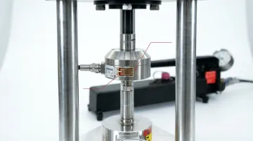
SensorData Technologies manufactures fatigue-rated load cells and force transducers for these environments, built from SAE 4340 alloy steel and guaranteed against fatigue failure across 100 million fully reversed cycles.
What Are Digital Sensors?
A digital sensor measures a physical quantity and converts the output to a discrete, binary-coded signal before transmitting it. A built-in analog-to-digital converter (ADC) samples the analog signal and quantizes it — resolution is determined by bit depth, with 12-bit, 14-bit, and 16-bit ADCs common in industrial applications.
How Digital Sensors Differ
Digital sensors differ in more than just output format. They typically include:
- Onboard signal processing — calibration coefficients, filtering, and linearization stored in the sensor itself
- Standardized communication interfaces — I²C, SPI, UART, Modbus RTU, CANopen, RS-485, and IO-Link (standardized under IEC 61131-9)
- Calibration data transmission — accuracy is embedded in the data stream, not dependent on external conditioning equipment
Smart sensors extend this further. These are digital sensors with embedded microprocessors capable of local computation, self-calibration, and in some cases wireless data transmission. In IIoT-connected environments, they enable automated condition monitoring — collecting and acting on machine data locally without routing every signal back to a central controller.
Cost and Complexity Tradeoffs
Digital sensors cost more upfront — the onboard ADC, microcontroller, and communications hardware add to unit price. But the downstream math often favors digital in large systems:
- No external signal conditioners required
- Simplified wiring, particularly in multi-sensor arrays on communication buses
- Reduced calibration labor over the sensor's lifetime
- Direct integration with PLCs and SCADA systems without additional hardware
Where Digital Sensors Fit
Digital sensors are the practical choice when:
- Dozens of sensors share a single controller — buses eliminate individual signal conditioning runs
- Cable runs exceed practical analog limits — digital protocols resist voltage drop and EMI over distance
- Data logging, automated alerting, or network integration are project requirements
- The application prioritizes system connectivity over raw measurement resolution — water/wastewater treatment, pharmaceutical GxP monitoring, and food processing are common examples
The industrial sensors market was valued at $27.97 billion in 2024 and is projected to reach $42.1 billion by 2029 at an 8.5% CAGR — growth driven largely by digital and smart sensor adoption across networked industrial environments.
Choosing the Right Sensor for Your Application
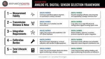
Neither sensor type wins universally. The right answer comes from evaluating five factors specific to your application:
- Measurement fidelity — Does your application require continuous signal capture, or is discrete sampling at defined intervals acceptable?
- Transmission distance and noise environment — Short runs in a controlled test cell favor analog; long cable runs through electrically noisy plant environments favor digital
- Integration requirements — Standalone DAQ setups work well with analog; networked PLC or SCADA systems push toward digital interfaces
- Calibration and maintenance burden — Digital sensors with onboard calibration reduce field maintenance; analog sensors require periodic loop calibration but offer simpler signal chains
- Total lifecycle cost — Component price is one input. Factor in signal conditioning hardware, wiring complexity, calibration intervals, and integration labor
Situational Guidance
Choose analog when:
- Continuous, high-fidelity real-time signal capture is critical — force, torque, and strain measurement in fatigue or structural testing
- Cable runs are short and the environment is controlled
- Your DAQ infrastructure already supports bridge-based or current-loop inputs
Choose digital when:
- The sensor must communicate with networked PLCs, SCADA, or building automation systems
- Long cable runs or electrically noisy environments threaten signal integrity
- Onboard calibration and automated data logging are priorities
The Hybrid Architecture
Many precision measurement systems don't force a binary choice. A proven configuration pairs high-fidelity analog sensors with high-resolution external ADCs and DAQ hardware. The analog sensor preserves signal continuity and dynamic response; the DAQ system handles digitization, processing, and storage.
NI's NI-9237 bridge module, for example, powers and measures up to four bridge-based sensors simultaneously, a standard architecture for strain gauge measurement in structural and component testing. HBK's QuantumX amplifiers handle full-bridge, half-bridge, and quarter-bridge configurations the same way. SensorData Technologies' sensors are designed for compatibility with both AC carrier and DC strain gauge signal conditioning electronics, integrating cleanly into this kind of hybrid measurement chain.
A Practical Scenario
Consider automotive suspension component fatigue testing. The test rig applies millions of fully reversed load cycles simulating road conditions. Three requirements define the sensor choice:
- Sub-millisecond response to capture peak loads accurately
- Continuous signal output across the full cycle range
- A mechanical design rated for the cycle count without recalibration
A strain gauge-based analog load cell is the right call here. A digital sensor's onboard processing introduces latency that can mask peak events; the ADC sampling rate sets a ceiling on dynamic response that an analog bridge simply doesn't have.
SensorData Technologies designs its fatigue-rated load cells for exactly this environment : 100 million fully reversed cycles guaranteed, with nonlinearity and hysteresis as low as 0.07% and deflection under 0.002 inches — the structural stiffness high-cycle fatigue testing demands.
If you're working through a sensor selection decision and need guidance on output type, cycle rating, or system integration, SensorData's engineering team offers direct technical consultation. With 30+ years in precision force and torque measurement and a 100% satisfaction guarantee, they can help you specify the right sensor for your application.
Conclusion
Analog and digital sensors solve different problems, and neither type dominates across the board. For continuous, high-precision force, torque, and strain measurement in demanding industrial test environments, analog remains the standard — strain gauge bridge physics suits these applications in ways current digital alternatives simply don't replicate. Where system integration, noise immunity, long-distance transmission, and automated monitoring take priority over raw measurement fidelity, digital sensors are the stronger choice.
Selecting the wrong type doesn't just affect performance metrics — it affects safety, data integrity, and operational cost across the full life of a test program. A sensor chosen for its unit cost rather than its fit can mean recalibration cycles that weren't budgeted, signal conditioning that wasn't planned, or data quality that undermines the test entirely. Match sensor architecture to what the application requires first, then evaluate cost within that constraint.
Frequently Asked Questions
What is an analog sensor?
An analog sensor measures a physical quantity and outputs a continuous electrical signal (voltage or current) proportional to the measured parameter. Common examples include thermocouples, strain gauge load cells, RTDs, and 4–20mA pressure transducers used in industrial process control.
What's the difference between digital and analog sensors?
Analog sensors output a signal that varies continuously with the measured quantity, capturing every change in real time. Digital sensors convert measurements into discrete binary values using an onboard ADC, offering better noise immunity and easier integration with control systems at the cost of some signal continuity.
What is an example of an analog sensor?
A strain gauge-based load cell is a common example — it outputs a millivolt-level signal proportional to applied force. A thermocouple outputs millivolts proportional to temperature, while an RTD delivers a resistance-based signal used in precision process monitoring.
Can analog sensors be converted to digital?
Yes. An analog-to-digital converter (ADC) samples the continuous signal and converts it to a binary value. DAQ systems routinely pair high-fidelity analog sensors with digital processing hardware, maintaining sensor accuracy while enabling digital integration.
What are the main disadvantages of analog sensors?
Analog sensors are susceptible to EMI and RFI, can drift due to temperature changes or component aging, and require loop calibration and external signal conditioning to maintain accuracy. These factors add integration complexity and maintenance overhead compared to digital alternatives.
Which sensor type is better for industrial force and torque measurement?
Analog sensors, particularly strain gauge-based load cells and force transducers, are generally preferred for industrial force and torque measurement. Their continuous high-fidelity output, fast dynamic response, and proven fatigue-rated reliability make them the standard choice for structural testing, fatigue analysis, and precision torque measurement.